7
v3.1 39
Option #22
Horn-Relay
Trunk-Relay
Trunk-Transistor
Horn-Transistor
Factory: Blue wire (+12 volt relay output) has Horn function & Green/
White wire (neg. transistor) has Trunk function
Option: Blue wire (+12 volt relay output) has Trunk function & Green/
White wire (neg. transistor) has Horn function
Option #23
Negative Door Pin
Positive Door Pin Switch
This option changes the polarity of GRAY/BLACK alarm input wire. (Most
Ford vehicles use a positive door pin switch.)
Option #24
Alarm
No Alarm
This feature can disable all alarm functions if the alarm features are not
desired.
Option #25
-18°C/0°F
-25°C/-13°F
This option changes the start temperature for the Vacation Option.
Option #26
Normal 3-Hour
5-Hour Interval
This option changes the minimum wait time between starts for the Vacation
Option.
Option #27
Normal
Auto Rearm
This option will automatically relock the doors and rearm the alarm if the
doors are not physically opened within 2 minutes of unlocking and disarming
the alarm with the transmitter.
Option #28
Normal
Silent Lock/Unlock Only
This option will remove the notification chirps for lock and unlock only. The
unit will still chirp for remote start.
Option #30
Normal
4-Pin Active During Remote
Running
The 4-pin external alarm sensor will be Active when the vehicle is remotely
running. If you are connecting a shock sensor to the unit, leave this option in
the normal factory setting. If you are using a "radar" sensor or additional pin
switches that are not affected by the motion of the vehicle starting, change
this option.
Option #31
Reset all Options
This option resets all options back to the factory settings.
PROGRAMMING AN OPTION
If you want the factory setting, DO NOTHING and skip this section. If you want
to change one or more of the features, TURN THE ON/OFF CONTROL SWITCH
TO THE “OFF” POSITION.
Wait for the red LED light to stop flashing
, then
continue with the following procedures:
A.
For options 1-9:
Push the white code button on the remote start module.
Each time you push the button the red LED light will flash 1 to 9 times
signifying at which feature you are (press it once, the LED light flashes
once. Press it again and it will flash two times. Press it again and it will
flash three times, etc., to show what feature you are at).
For options 10-19:
Push the red code button on the remote start module.
You will see the LED light flash a long blink. This is option 10. You can
scroll to option 11 by pressing the white button once – you will see a
long blink followed by one short blink. You can scroll to option 12 by
pushing the white button again – one long and two short blinks brings
you to option 12.
For options 20-29:
Push the red code button twice to get the two long
blinks – you are now at option 20. Push the white button to jump ahead
to option 21 – two long blinks and one short blink. Push three more
times to get to option 24 – two long and four short blinks.
For options 30-31:
Push the red code button three times to get three
long blinks – you are now at option 30. Push the white button once to
jump to option 31 (three long blinks and one short blink).
B.
When you are at the feature level you desire,
push the start button on
the transmitter for one second
and the red LED light will flash
once to
signify you are at the Option setting.
You can push the start transmitter
button again and it will flash
twice to signify you are at the Factory
setting.
Push the start transmitter button again and you will go back to
the Option setting.
C.
You can choose to change another feature by starting over again at Step
A. After six seconds, the remote starter automatically exits the
programming mode (three LED light flashes).
D.
When finished – switch the Control Switch back ON. The red LED light
will flash once.
SPECIAL CASES
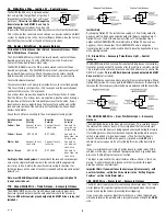
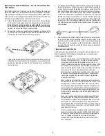
1. How to Use a Relay
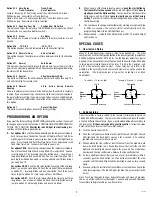
Many of the optional steps require a relay to be hooked up. The most
common relay used for this type application is the Bosch type relay (DesignTech
#20043 or Radio Shack Cat.# 275-226). Use the diagram below for a typical
hookup. If you have another relay then you need to know that pins 85 and 86
in this diagram relate to the coils of the relay. Pin 30 is the ‘common’, and
pin 87 is the ‘normally open’ contact. If your relay has a pin 87A in the
middle it is the normally closed contact and may or may not be used in the
application. (The diagram below is typical for an Ignition 3 or trunk
application).
To 12 volt output
To supply Ground (-) output
From
Remote
Starter
(-)
To Vehicle's Accessory
+12 V
87
86
85
30
To Ground
To Vehicle's Accessory
+12 V
87
86
From
Remote
Starter
(-)
85
30
+12 V
2. Code Learning
Your transmitter is factory coded to the remote starter
module with over
16,000,000 different codes. The remote starter module can learn the codes
of up to 4 different transmitters. If you want to add additional transmitters to
the receiver or
if it does not respond to your transmitter
– follow the steps
below to teach the receiver the transmitter code(s):
A.
Turn the Control Switch ON.
B.
Push the red "code learn" button to the right of the red LED light. The red
LED light and the dash lights come on for a second. (The vehicle's
ignition and accessory wires come on).
C.
While holding the transmitter at least three feet from the module, hold
down the Start button (on a five button transmitter) until the red LED
light and the dash lights come on again for a second. The module has
now learned the transmitter code. Release the transmitter button.
D.
To learn additional transmitters (up to 3 more), immediately (within 5
seconds) push the Start button (on a five button transmitter) for a few
seconds until the red LED light and the dash lights come on for a second
again.
E.
5 seconds after the last time the transmitter was learned the unit exits the
code-learning stage. (The red LED light, ignition and accessories flash 4
times).
Note:
Teaching the module a new transmitter code will erase all previous
codes - so all transmitters must be taught. You have only 5 seconds between
transmitters to begin teaching a new transmitter.

