background image

M

AINTENANCE


LBB Series Oven Owner

’s Manual 

42 


Version 


20


6.3.2.  Decontaminating the LBB Series Oven  


Notice


Before using any cleaning or decontamination method except 
those recommended by the manufacturer, users should check 
with the manufacturer that the proposed method will not 
damage the equipment. 


For best results, decontaminate the work zone daily. 

1.


Wipe all work surfaces with an appropriate disinfectant.  

2.


Use a neutral cleaning agent. Do not use acidic or chlorine cleaning detergents as they 
may damage or corrode the oven.  


If necessary, remove highly contaminated inner chamber parts 
for cleaning or exchange.  


6.4.  Routine Tests 


Danger! 


Failure to heed warnings in this instruction manual and on the 
oven could result in personal injury, property damage or death. 


Test LBB Series oven functions regularly and carefully for best performance. Safety of personnel 
and maintenance of your equipment may depend on the proper operation of any of the 
temperature control functions.  


Warning! 

 
Do not decontaminate oven without first disconnecting power. 
Ensure adequate personal safety while decontaminating oven. 


Danger! 


Explosive gases may form during decontamination. Dry and 
ventilate oven before start-up to avoid explosions.  

Summary of Contents for LBB 1-23

Page 1: ...LBB Series Oven Owner s Manual PREFACE Version 20 LBB SERIES OVEN OWNER S MANUAL C 188 PN 336979 VERSION 20 4 2018...

Page 2: ...AND SPARE PARTS LISTS section Corrected Despatch address K Parts lists corrections in DRAWING AND SPARE PARTS LISTS section L Updated warranty 12 3 2011 Livingston Revise format 13 9 2011 Livingston...

Page 3: ...LBB Series Oven Owner s Manual PREFACE Version 20...

Page 4: ...PREFACE LBB Series Oven Owner s Manual 4 Version 20...

Page 5: ...ts 18 2 7 2 Disconnecting Hard Wired Units 18 2 7 3 Disconnecting Corded Units 19 2 7 4 Disconnecting Units with Optional Disconnect Switch 19 3 Theory of Operation 20 3 1 The LBB Series Oven 20 3 1 1...

Page 6: ...ng and Decontamination 41 6 3 1 Cleaning the LBB Series Oven 41 6 3 2 Decontaminating the LBB Series Oven 42 6 4 Routine Tests 42 6 4 1 Test Control Instrument 43 6 4 2 Test High Limit Instrument 43 6...

Page 7: ...ring Rear View 46 Figure 16 Prepare to remove control instrument by removing the mounting bracket 47 Figure 17 Connections to Control Instrument 47 Figure 18 High Limit Connector Block on Control Boar...

Page 8: ...espatch Industries Despatch Industries does not assume any responsibility for any errors that may appear in this manual In no event will Despatch Industries be liable for technical or editorial omissi...

Page 9: ...worldwide Despatch products are backed by a drive for long term customer satisfaction and a strong sense of responsibility The worldwide network of factory trained Service Professionals is available t...

Page 10: ...tuation that if not avoided will result in death or severe injury Warning Warning is the signal word used to indicate a hazardous situation that if not avoided could result in death or severe injury C...

Page 11: ...43 109 45 114 51 130 2 on 2 5 16 2 NOTE refer to assembly drawing for exact dimensions The LBB oven is not intended to process solvents or other volatile or flammable materials Oven exhaust is intend...

Page 12: ...181 600 272 600 272 600 272 Maximum Shelf Load Lbs Kgs 50 23 200 91 200 91 200 91 200 91 Exhaust Capacity CFM LPS 1 0 5 3 1 4 12 5 7 14 6 6 14 6 6 LBB1 69 and larger models have reinforced shelves Ma...

Page 13: ...ase Heater KW Cord and Plug LBB 1 23 120 11 6 50 60 1 1 2 Included 15 Amp LBB 1 23 240 5 8 50 60 1 1 2 Included 15 Amp LBB 1 69 120 21 6 50 60 1 2 4 None Hardwired LBB 1 69 240 10 8 50 60 1 2 4 None H...

Page 14: ...very time as measured at control thermocouple Dampers must be open to operate at the minimum temperature Time to Temperature and Temperature Uniformity values are based on 240V 60 Hz operation with co...

Page 15: ...rce that can energize any element of the LBB Series oven must be shut off at the closest possible power source This includes air water and electricity including the Disconnect Switch 2 After energy so...

Page 16: ...different sizes of ovens LBB1 23 Four people lift oven s lower corners and place on wheeled transport pallet Push pallet to desired site and lift oven from pallet again lift using lower corners LBB1 6...

Page 17: ...isconnect 4 Shut off fuel 5 Call the fire department or use a fire extinguisher to extinguish the fire Danger Always disconnect all power before extinguishing a fire Attempting to extinguish a fire in...

Page 18: ...permanently connected hard wired ovens include models LBB1 69 LBB2 12 LBB2 18 and LBB2 27 Permanently connected and multi phased equipment must employ a switch or circuit breaker as means for disconn...

Page 19: ...ug the cord from the power source 2 7 4 Disconnecting Units with Optional Disconnect Switch The LBB Series oven has an optional Disconnect Switch Figure 1 This Disconnect Switch is located on the fron...

Page 20: ...h precise digital control to deliver fast processing The overall result is efficient productivity under strenuous conditions The LBB Series ovens are precise and practical The unique Despatch design m...

Page 21: ...ng temperature changes at the sensor location However overall chamber temperature remains stable The strategic location of the sensor compensates for delays in heat convection and enhances the perform...

Page 22: ...ns Features Description OP1 Output 1 status value OP2 normally not used for LBB Ovens C F Degree indicator Celsius or Fahrenheit PV Process value HSP1 High Limit setpoint 1 LSP1 typically not used for...

Page 23: ...operates as a dual functioning controller High Limit instrument The control portion utilizes a time proportioning voltage signal to control heating devices with minimal temperature fluctuations The Hi...

Page 24: ...mage occurred during shipping Contact the shipper immediately and file a written damage claim Contact Despatch Industries 1 800 473 7373 or 1 952 469 8230 or service despatch com to report your findin...

Page 25: ...er source indicated on the specification nameplate 3 Plug or hardwire oven directly to the electric supply 4 2 3 Wiring Power Connections Read the Model LBB nameplate top of oven or top of control are...

Page 26: ...69 and LBB2 12 18 27 must be hardwired to the electric supply using 10 AWG or larger wires suitable for at least 75 C 167 F To wire the LBB Series oven for units requiring hardwiring 1 Remove the top...

Page 27: ...ASSEMBLY SETUP Version 20 27 2 Run the wire through the rear access hole Figure 9 and connect the appropriate wires at the connector block Figure 10 Figure 9 Wiring Access through Rear of Oven Figure...

Page 28: ...e quality of the product being processed The purchaser and operator are responsible ensure that the product undergoing processing in a Despatch oven is adequately protected from damage Carefully follo...

Page 29: ...ubstance or liquid in this oven because they may explode under heat Know the system Read this manual carefully Make use of its instructions and explanations Safe continuous satisfactory trouble free o...

Page 30: ...exhaust vent to desired opening by adjusting the damper at the rear of the oven Figure 12 a Adjust the vent for maximum performance at various operating temperatures 3 Enter desired setpoint on the Hi...

Page 31: ...tpoint OUT cycles ON and OFF to maintain the temperature setpoint b OUT lights when the control calls for heat 6 Turn HEATER OFF after the heating cycle is complete 7 Do not turn the fan OFF until the...

Page 32: ...nformation for changing setpoints programming modes and displaying temperature along with instructions for oven zone calibration parameter setup mode and troubleshooting 5 4 1 Change Setpoint Warning...

Page 33: ...seconds 2 Press until the desired parameter displays See Table 4 for more information 3 Press or to display the value 4 Use or to move to the desired setting 5 Press to enter the value 6 Press and hol...

Page 34: ...o LoC 1 allowing only the setpoint to be changed This setting prevents inadvertent changing of control parameters If necessary to alter control parameters change the LoC 1 to LoC 0 See Section 5 4 2 1...

Page 35: ...value a In displays b Press the or to enter the parameter c Note If unable to change setup parameters follow this procedure i Press and hold for three 3 seconds to return to the operation mode ii Chan...

Page 36: ...s programmed in the Control instrument is set to 0 For more information on programming parameters refer to Section 5 4 2 1 3 Locate the temperature sensor of the temperature measuring device at the ce...

Page 37: ...selection 5 4 5 1 Change the High Limit Instrument Setpoint Warning Never operate oven at a temperature in excess of the maximum operating temperature of 204 C 400 F Enter setpoint on the High Limit i...

Page 38: ...s press The High Limit instrument automatically exits Setup mode if no keys are pressed for about two 2 minutes 5 4 7 High Limit Instrument Setup Parameters Table 6 explains the High Limit instrument...

Page 39: ...hrenheit Warning Changing program parameters alters the function of the Control Proceed carefully and fully understand each parameter before changing that parameter Configure the High Limit instrument...

Page 40: ...esults Keep all equipment accessible Do not permit other materials to be stored or piled against it Protect controls against excessive heat particularly controls motors or other equipment containing e...

Page 41: ...sms bearing or wear surfaces should be lubricated to ensure easy operation 6 3 Cleaning and Decontamination 6 3 1 Cleaning the LBB Series Oven For best product results clean the oven monthly To clean...

Page 42: ...e or corrode the oven If necessary remove highly contaminated inner chamber parts for cleaning or exchange 6 4 Routine Tests Danger Failure to heed warnings in this instruction manual and on the oven...

Page 43: ...2 Test High Limit Instrument Test the High Limit instrument every 40 hours With the oven operating at a set temperature set High Limit instrument down to the setpoint operating temperature The High Li...

Page 44: ...RA Material Return Authorization number Attach the MRA number to the returned part for identification When ordering parts expedite the process by having the model number serial number and part number...

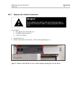
Page 45: ...5 1 Replace the Control Instrument Danger Do not attempt any service on this oven before opening the main power disconnect switch or removing all power from the oven Tools needed One quarter 1 4 inch...

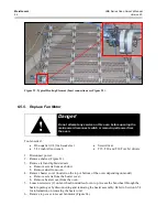
Page 46: ...ven door and oven ceiling 4 Remove wires from the old control instrument using P1 Phillips screwdriver carefully noting which wires connect to which terminals Figure 15 Thermocouple wires Control Inst...

Page 47: ...unting bracket back and off Figure 16 6 Remove old Control instrument from the panel 7 Install new Control instrument into the control panel 8 Secure instrument mounting bracket 9 Reattach wires to th...

Page 48: ...ve four screws from the face of the control panel Figure 13 3 Slide the panel forward Figure 14 4 Remove wires from the old High Limit instrument carefully noting which wires connect to which terminal...

Page 49: ...ument connector plug to the circuit board Figure 18 11 Reattach thermocouple wires Make sure that the wires are connected correctly Figure 15 See Figure 20 for correct High Limit instrument connection...

Page 50: ...e duct from oven 4 Remove heater cover located on the top or bottom of the oven depending on model a Remove screws from the heater cover b Remove heater cover from the oven 5 Disconnect heater leads f...

Page 51: ...1 Flat washer Terminal Ring Flat washer Hex nut Lock washer Insulator Install terminals as shown to prevent possible electrical shorts and or stress on terminals Angle tolerance 15 Front View Side Vie...

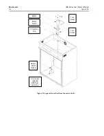
Page 52: ...e left and right side ducts a Remove screws from each duct b Remove duct from oven 4 Remove heater cover located on the top or bottom of the oven depending on model a Remove screws from the heater cov...

Page 53: ...motor mount off old motor 10 Put motor mount onto new motor T20 Torx bit driver 11 Replace fan motor a Reattach motor to oven body b Reattach motor lead plug to circuit board 12 Replace top cover 13...

Page 54: ...CE LBB Series Oven Owner s Manual 54 Version 20 Fan wheel spaced 0 25 from inside top Motor shaft sleeve Tinnerman clip Motor mount Motor Torx screw Torx screw Figure 25 Separate fan wheel from fan mo...

Page 55: ...e vent Fan motor failure Replace fan motor Frequent heater element burnout Harmful fumes generated by load Increase vent opening or discontinue process Spillage or splattering of material on heater el...

Page 56: ...nto top or bottom latch only Uneven latch tension adjustment Ensure that latch strike is contacting center of latch Adjust mounting angle as required Adjust door for even top and bottom latch tension...

Page 57: ...e Control Mode CtL must be first set to PID k Once you have verified each of the parameters go to the LOC parameter and change the value to 1 one to lock the parameters but still allows the set point...

Page 58: ...LED ON If it is then the hi limit is tripped and needs to be reset or the parameters need to be verified b Press RESET key for several seconds until the LOCK LED goes out c If the OP1 LED is still on...

Page 59: ...LAC LFC Series Oven Owner s Manual APPENDICES Version 20 59 8 Appendices 8 1 Standard Products Warranty http www despatch com pdfs standard_warranty pdf 8 2...

Page 60: ...mets mount into the forward set of rear holes b On LBB2 12 stands the rear grommets mount into the set of holes closest to the rear of the stand 2 Place the oven on top of the stand The four embossed...

Page 61: ...ICES Version 20 61 8 3 2 End of Cycle EOC Timer Option Use the timer option to count down in hours toward powering the heater OFF Figure 27 Actual timer may vary from the model pictured Figure 27 Figu...

Page 62: ...APPENDICES LAC LFC Series Oven Owner s Manual 62 Version 20 8 3 3 Operating the Timer...

Page 63: ...LAC LFC Series Oven Owner s Manual APPENDICES Version 20 63...

Page 64: ...on 8 5 shows the wiring for this option 8 3 6 High Alarm Limit Option The High Alarm Limit option sounds an alarm and turns on a light when a High Limit condition occurs Silence the alarm horn by pres...

Page 65: ...al Schematics See the electrical schematics included on the manual CD The drawings included are intended to be reference only and the latest revision may be found online at www despatch Copyright 2018...

Reviews: