18
In order to reset the limit relay, the process value must not exceed the limit setpoint.
Pressing the RESET key with the control in this state will reset the limit relay, and the
OUT indicator will turn off.
NOTE: The hysteresis limit value in the setup mode affects the value at which the
control will reset. In the event of a high limit condition, the high limit setpoint must be
higher than the sum of the process value and the hysteresis value. In the event of a
low limit condition, the process value must be higher than the sum of the low limit
setpoint and the hysteresis value.
3.6 Annunciator
An additional (optional) annunciator output is available. If selected in Program mode
(either for USE2 or USE3) the annunciator output operates as follows:
If the limit is, or has been, exceeded AND the Reset key has NOT been pressed since
the limit was exceeded, then the annunciator output will be active.
If the Reset key is pressed while the limit is exceeded, the annunciator output will be
deactivated, even if the limit remains being exceeded.
3.7 Remote Reset (Optional)
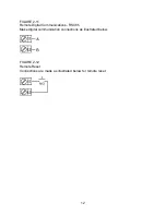
The Remote Reset option allows a dry contact closure to substitute for the front panel
Reset switch. Operation is as follows:
If the option “rrES” (remote reset) is selected then:
A contact closure will simulate the action of the front panel reset switch.
A contact opening will have no effect.
If the external contacts are left closed, only ONE reset operation will occur. If the
instrument subsequently goes into a state where reset is required again, the contacts
must be opened and closed again. The front panel Reset switch can still be used to
activate a reset if required.
Summary of Contents for MIC 1162
Page 2: ......
Page 4: ...ii...
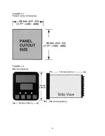
Page 8: ...4 FIGURE 2 1 Panel Cut Out Dimensions FIGURE 2 2 Main Dimensions...
Page 26: ...22...
Page 30: ...26...
Page 34: ...30...
Page 36: ...32...
Page 40: ...36...
Page 41: ...37 APPENDIX A BOARD LAYOUT JUMPER POSITIONING FIGURE A 1 Exploded View Board Layout...
Page 42: ...38 FIGURE A 2 CPU PWA...
Page 43: ...39 FIGURE A 3 OPTION PWA DC OUTPUT 2 OUTPUT 3...
Page 44: ...40...
Page 48: ...44...
Page 54: ...50...

