33
SECTION 9: CALIBRATION
NOTE: Calibration should be attempted only on instruments on which calibration errors
have been encountered (see calibration check).
EQUIPMENT REQUIRED:
1.
Input source with accuracy better than +/- 0.05% of reading.
a.
Thermocouple:
T/C simulator, K type with compensated leads
b.
DC:
0 to 50 mV OR
0 to 10 V
OR
0 to 20 mA
c.
RTD:
Decade resistance box with 3 wire input
2.
MIC1162 case wired for appropriate input voltage supply (90 to 264 VAC, 50/60
Hz)
PROCEDURE:
1.
Before applying power, position the input conditioning jumpers on the CPU PWA
as appropriate. See Figure A-1 and A-2 in Appendix A.
2.
Connect the appropriate input from the Input Source. Set the Input Source as
follows:
INPUT TYPE
INPUT SOURCE
DC 0 - 50 mV
50 mVDC
DC 0 - 10 V
10 VDC
DC 0 - 20 mA
20 mADC
RTD
200 ohms
T/C (Type K)
0
°
C
3.
Apply power to the instrument and leave powered for five (5) minutes for RTD
and DC inputs OR thirty (30) minutes for T/C inputs, then power down.
Summary of Contents for MIC 1162
Page 2: ......
Page 4: ...ii...
Page 8: ...4 FIGURE 2 1 Panel Cut Out Dimensions FIGURE 2 2 Main Dimensions...
Page 26: ...22...
Page 30: ...26...
Page 34: ...30...
Page 36: ...32...
Page 40: ...36...
Page 41: ...37 APPENDIX A BOARD LAYOUT JUMPER POSITIONING FIGURE A 1 Exploded View Board Layout...
Page 42: ...38 FIGURE A 2 CPU PWA...
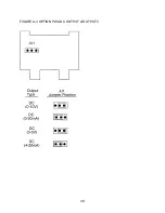
Page 43: ...39 FIGURE A 3 OPTION PWA DC OUTPUT 2 OUTPUT 3...
Page 44: ...40...
Page 48: ...44...
Page 54: ...50...


