3
SECTION 2: INSTALLATION AND WIRING
2.1 General Information
Electrical code requirements and safety standards should be observed and installation
performed by qualified personnel.
The electronic components of the instrument may be removed from the housing during
installation. To remove the components, grip the side edges of the front panel and pull
the instrument forward. During re-installation, the vertically mounted circuit boards
should be properly aligned in the housing.
Ensure that the instrument is correctly orientated. A stop will operate if an attempt is
made to insert the instrument incorrectly.
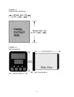
Recommended panel opening sizes are illustrated in Figure 2-1. After the opening is
properly cut, insert the instrument into the panel opening. Ensure that the panel gasket
is not distorted and that the instrument is positioned squarely against the panel. Slide
the mounting clamp into place on the instrument and push it forward until it is firmly in
contact with the rear face of the mounting panel.
Note: The mounting clamp tongues may engage either on the sides or the
top/bottom of the instrument housing. Therefore when installing several
instruments side-by-side in one cut-out, use the ratchets on the top/bottom
faces.
Summary of Contents for MIC 1162
Page 2: ......
Page 4: ...ii...
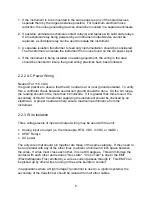
Page 8: ...4 FIGURE 2 1 Panel Cut Out Dimensions FIGURE 2 2 Main Dimensions...
Page 26: ...22...
Page 30: ...26...
Page 34: ...30...
Page 36: ...32...
Page 40: ...36...
Page 41: ...37 APPENDIX A BOARD LAYOUT JUMPER POSITIONING FIGURE A 1 Exploded View Board Layout...
Page 42: ...38 FIGURE A 2 CPU PWA...
Page 43: ...39 FIGURE A 3 OPTION PWA DC OUTPUT 2 OUTPUT 3...
Page 44: ...40...
Page 48: ...44...
Page 54: ...50...


