background image

E105, 313327, REV A 


Protocol 3

TM

 User Guide 

76 of 82 

©2021 ITW EAE. All rights reserved. Despatch is a registered trademark in the U.S. and other 
countries.


No part of the contents of this manual may be reproduced, copied or transmitted in any form 

or by any means without the written permission from ITW EAE, unless for purchaser's personal use.


7.


MAINTENANCE 


Danger! 

Do not attempt any service on this oven before opening the main 
power disconnect switch or removing all power from the oven. 


7.1.


Checklist  


Keep equipment clean. Gradual dirt accumulation retards airflow and cooling 
of electronics components inside device. 


Keep equipment accessible. Do not permit other materials to be stored or 
piled against it. 


Protect equipment against excessive heat. Avoid temperatures greater than 
40°C (104°F). 


Establish maintenance and checkup schedules. Do this promptly and follow the 
schedules faithfully. 

7.2.


Replacement 

To order or return part, contact ITW EAE Service and Technical Support. (Visit 

www.despatch.com

 or refer to the last page of this manual for contact 

information.) When returning parts, an ITW EAE representative will provide a 
Return Material Authorization (RMA) number. Attach the RMA number to the 
returned part for identification. When ordering parts, expedite the process by 
having the model number, serial number, and part number on hand.  


Summary of Contents for PROTOCOL 3

Page 1: ...PROTOCOL 3 Controller USER GUIDE E105 PN 313327 REVISION A 01 2021...

Page 2: ...N PREPARED BY CHECKED BY DATE 1 1 K Livingston 03 2013 DESCRIPTION Modified instructions for delayed start and remote communication Modbus User s Programming Manual added E 106 PN320813 Version 3 2013...

Page 3: ...FICATIONS 10 2 1 Process Input 10 2 2 Outputs 12 2 3 Operating Conditions 12 2 4 Conformance Norms 13 2 5 Display 13 2 6 Data Recorder 14 3 SAFETY 15 3 1 General Safety Information 15 3 2 Lockout 15 3...

Page 4: ...ming Worksheet 52 6 4 Recorder Control 53 6 5 USB Menu 54 6 5 1 Working with USB Memory Stick Folders and Files 56 6 5 2 File Naming Conventions 57 6 5 3 Create a New Name before Writing to the USB De...

Page 5: ...Figure 10 Protocol 3 Ethernet communication check 27 Figure 11 Protocol 3 Ethernet controller online 28 Figure 12 Select a Mode Display 31 Figure 13 Manual Mode Display Screen 35 Figure 14 Timer Mode...

Page 6: ...5 Display 13 Table 6 Data Recorder 14 Table 7 Protocol Plus to Protocol 3 Controller Conversion 23 Table 8 Keypad Buttons and Functions 32 Table 9 LEDs and Functions 34 Table 10 Sub Menu Descriptions...

Page 7: ...EAE Despatch does not assume any responsibility for any errors that may appear in this manual In no event will ITW EAE Despatch be liable for technical or editorial omissions made herein nor for dire...

Page 8: ...Despatch products are backed by a drive for long term customer satisfaction and a strong sense of responsibility The worldwide network of factory trained Service Professionals is available to support...

Page 9: ...ipment Danger Danger is the signal word used to indicate a hazardous situation that if not avoided will result in death or severe injury Warning Warning is the signal word used to indicate a hazardous...

Page 10: ...ply voltage influence negligible within supply limits Humidity Influence Negligible if non condensing Process Display Displays up to 5 over and 5 under span limits Process Variable Input Offset Readin...

Page 11: ...C584 Supported RTD Types Ranges Type Range C Range F 3 Wire PT100 199 to 800 C 328 to 1472 F NI120 80 to 240 C 112 to 464 F Optional decimal place can be displayed up to 999 9 C F RTD Calibration 0 1...

Page 12: ...ating Single pole single throw SPST 2A resistive at 120 240VAC Lifetime 200 000 operations at rated voltage current Isolation Basic Isolation Linear DC Resolution 8 bits in 250mS 10 bits in 1s typical...

Page 13: ...tem Description EMI CE Complies with EN61326 Safety Considerations CE Complies with EN61010 1 UL cUL to UL61010C 1 Pollution Degree 2 Installation Category II Front Panel Sealing IP65 rating IP20 behi...

Page 14: ...a Recorder Table 6 Data Recorder Item Description Recording Memory 1Mb non volatile flash memory Data retained when power is turned off Recording Interval 1 2 5 10 15 30 seconds or 1 2 5 10 15 30 minu...

Page 15: ...aining or repairing the Protocol 3 controller An accidental start up while working on the Protocol 3 controller can result in serious injury or death 3 2 1 Lockout Requirements 1 Every power source th...

Page 16: ...lectrical repair Danger Contact with energized electrical sources may result in serious injury or death Before performing maintenance disconnect all electrical power from the machine Use a padlock and...

Page 17: ...the contents of this manual may be reproduced copied or transmitted in any form or by any means without the written permission from ITW EAE unless for purchaser s personal use 17 of 82 4 Extinguish th...

Page 18: ...ocessed has a critical high temperature limit the high limit set point should be set to a temperature somewhat below the temperature at which the product could be damaged If the product does not have...

Page 19: ...eater output when tripped The High Limit temperature is displayed as HLPV Manual Mode only If the high limit trips the Hi Limit indicator will light and the relay must be manually reset Allow the oven...

Page 20: ...proportional to the process temperature setpoint or control power o 0 5V o 0 10V o 2 10V o 020 ma o 4 20 ma o 0 10VDC Power Supply The signal can be an input to other devices such as a chart recorder...

Page 21: ...ritten permission from ITW EAE unless for purchaser s personal use 21 of 82 Protocol Plus Rear Panel Protocol 3 Rear Panel Former Power Connections New Power Connections Former SSR and Hi Limit Connec...

Page 22: ...tempting any repair or adjustment 5 1 Install the Protocol 3 Controller When replacing a Protocol 3 controller follow the steps below Tools required for installation include socket set with 1 bit 2 Ph...

Page 23: ...rminals 17 18 Hi limit Thermocouple Terminals 15 16 Hi limit Thermocouple Terminals 32 33 5 3 Setting up Remote Communication Remote communication between the Protocol 3 controller and a PC running th...

Page 24: ...MAC Address for more information on retrieving the MAC address On the Protocol 3 control remove the back plate to access the circuit board area of the control and record the MAC address listed on the...

Page 25: ...navigate to the top System menu and select Set IP Address Figure 6 Figure 6 Protocol 3 Set IP Address 6 Enter the MAC address found on the Ethernet communications card in the Protocol 3 control Also e...

Page 26: ...sonal use 7 To test if the controller s IP address has been correctly assigned press the Search Network icon and the newly configured controller should be listed Figure 8 Figure 8 Protocol 3 Ethernet...

Page 27: ...displayed double check software controller settings and wiring Contact ITW EAE Despatch support for additional details if the control will not communicate with the Protocol Manager software properly F...

Page 28: ...part of the contents of this manual may be reproduced copied or transmitted in any form or by any means without the written permission from ITW EAE unless for purchaser s personal use 12 The control s...

Page 29: ...ypically the Protocol 3 controller rear cover must be removed to retrieve the Ethernet module MAC address The following steps to retrieve the MAC address can be used as an alternative on a new control...

Page 30: ...roduced copied or transmitted in any form or by any means without the written permission from ITW EAE unless for purchaser s personal use 8 Type the command arp a 9 In the ARP list look for a MAC addr...

Page 31: ...ds and other safety rules and regulations of state and local governments Refer to the relevant safety standards in OSHA and National Fire Protection Association NFPA Section 86 of 1990 6 1 User Contro...

Page 32: ...item on the list Editable values Press to decrease Press and hold to speed the change Trend View press to move the Cursor Line back through stored data points Navigate up through menu parameter lists...

Page 33: ...controlling output Reset Latched High Limit relay if below alarm condition If High Limit alarm is active press to release the High Limit relay NOTE This switch releases the High Limit relay only if t...

Page 34: ...unning Timer LED When lit indicates a timer is currently running Manual LED When lit indicates the controller is in Manual Mode Cycle Complete LED When lit indicates the controller is currently stoppe...

Page 35: ...ect a Mode This screen allows the choice of manual mode timer mode or profile mode Regularly backup critical system data according to your company policies Be sure to back up configuration and profile...

Page 36: ...ct and highlight the menu item c Press d Press or to change values e Press to select the value 4 Manual Mode allows you to set event relay status a Press or to navigate to and select the appropriate r...

Page 37: ...change value 5 Press to enter the desired value 6 Timer Mode allows you to set event relay status a Press or to navigate to and select the appropriate relay Figure 13 b Press to toggle the relay ON an...

Page 38: ...HLSP to set the High Limit Setpoint before running a profile Use Profile Mode to select and run profiles that are programmed into the unit Figure 15 Press or to navigate to select the highlighted prof...

Page 39: ...Figure 12 by 1 Simultaneously press and 2 Press or to navigate to select the highlighted option 3 Press to enter that mode Table 10 Sub Menu Descriptions Menu Item Description Mode Selection Return to...

Page 40: ...Section 6 5 1 for more information Use Profile Setup to create edit and delete profiles Figure 17 Access the Profile Setup from the Main Menu screen The Profiler option allows storage of up to 255 pr...

Page 41: ...41 of 82 Table 11 Profile Setup Options Menu Item Description General Configuration Enable remote Profile control and Profile automatic start Create a Profile Create profile Edit a Profile Header Cha...

Page 42: ...Despatch is a registered trademark in the U S and other countries No part of the contents of this manual may be reproduced copied or transmitted in any form or by any means without the written permis...

Page 43: ...ter a Profile Name Unique name for each profile using up to 8 characters 4 Profile Start Trigger None Profile start not delayed After Delay Set hours and minutes to delay before starting the profile D...

Page 44: ...ntigrade Set the segment ramp rate in units per hour Set the Auto Hold Type None Above Setpoint Below Setpoint Band Set Events 1 5 Press or to toggle between Active and Inactive 9 Step Set the target...

Page 45: ...r numbering of times to repeat sequence choose from Control Off Maintain Last Profile SP Control Off with Events 6 3 1 Prepare for Profile Setup From the Select a Mode screen simultaneously press and...

Page 46: ...without the written permission from ITW EAE unless for purchaser s personal use When programming an oven with a gas fired heater note that the burner can be started manually or by programming a profil...

Page 47: ...is a registered trademark in the U S and other countries No part of the contents of this manual may be reproduced copied or transmitted in any form or by any means without the written permission from...

Page 48: ...press and to display the Main Menu 1 Navigate to and highlight Profile Setup 2 Press to display Profile Setup Enter Profiler Mode Unlock Code screen 3 Press to enter Factory Unlock Code 0010 4 Press...

Page 49: ...ment Ramp Time a Press or navigate to 1 hour 01 00 00 b Press as needed to complete the entry 17 For Auto Hold Type when None is highlighted press to complete the entry 18 For Event 1 5 press as neede...

Page 50: ...ess or navigate to 2 hours 02 00 00 b Press as needed to complete the entry 28 For Auto Hold Type when None is highlighted press to complete the entry 29 For Event 1 5 press as needed to accept Inacti...

Page 51: ...ase Release with Key press At Time Of Day or via a Digital Input Start from Value 1st segment starts from current setpoint or current PV input value Delayed Start After 0 to 99 59 hh mm time delay or...

Page 52: ...s of this manual may be reproduced copied or transmitted in any form or by any means without the written permission from ITW EAE unless for purchaser s personal use 6 3 4 Programing Worksheet Profiles...

Page 53: ...ol from the Main Manu 1 Navigate to and highlight Recorder Control 2 Press to display Recorder Control Enter Data Recorder Unlock Code screen 3 Press as necessary to enter Factory Unlock Code 0010 4 P...

Page 54: ...ected to the unit using the front USB port Figure 23 Access the USB Menu from the Main Menu See Table 15 for USB Menus options Regularly backup critical system data according to your company policies...

Page 55: ...sonal use 55 of 82 Menu Item Description Write Recorder Log File Writes recorder Log data to USB Read Profile File Read profile from USB device to unit Write Profile File Write profile from unit to US...

Page 56: ...stick CONFIG Configuration files bct PROFILE Profile program files pfl RECORDER Recorder log folders and files The user is asked for a new recorder subfolder name before transferring recorder data to...

Page 57: ...a lines the Protocol 3 controller creates a new file with the last digit incremented by 1 for instance 000001 2 csv then 000001 3 csv During Data Transfer normal operation carries on in the background...

Page 58: ...e or folder 6 6 Configuration Menu Configuration provides access to menus that allow for setting up 11 different options 1 Input Input settings and calibrate for process and High Limit Inputs 2 Contro...

Page 59: ...ademark in the U S and other countries No part of the contents of this manual may be reproduced copied or transmitted in any form or by any means without the written permission from ITW EAE unless for...

Page 60: ...Control Input Calibration Factory Calibration Single Point Calibration OFF 400 400 Two Point Calibration Low Temp Low Offset High Temp High offset High Limit Input Setup Input Type Thermocouples PtRh...

Page 61: ...sage Set the desired type for any Linear Outputs fitted From 0 5 0 10 1 5 2 10V 0 20 4 20mA or 0 10VDC adjustable Transmitter PSU Parameters Unused Retransmit PV Retransmit SP Control Power Alarm Set...

Page 62: ...yyyy or mm dd yyyy Set Date Set Day of Week Choose day of week Set Time hh mm ss format Display Set options language screen color inverted display Display Configurations Language English or Alternate...

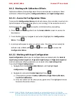
Page 63: ...s and from Select a Mode to access the Main Menu 3 From the Main Menu navigate to Configuration Menu using and Highlight Configuration Menu and press 4 At the Enter Configuration Mode Unlock Code prom...

Page 64: ...nge Per Min Alarm Value Degrees Minimum Duration Seconds Alarm Inhibit Input Signal Break N A N A N A Control Loop Loop Alarm Type Manual Loop Alarm Time mm ss active only if loop alarm type is manual...

Page 65: ...n Section 6 6 1 1 Accessing Configuration Menu 2 From the Configuration Menu navigate to and select Alarm Configuration 3 Navigate and select Process High for Alarm 1 Type and press 4 Navigate to chan...

Page 66: ...vate Loop Alarm A loop alarm detects faults in the control feedback loop by continuously monitoring process variable response to the control output s If one of the five alarms is defined to be a loop...

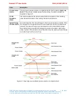
Page 67: ...larm activates as depicted in Figure 27 PV SP Deviation Alarm The control subtracts the process value from the setpoint If the resulting value exceeds the alarm value setting the alarm will activate S...

Page 68: ...e controller before proceeding 1 Press and together from the Select a Mode screen to access the Main Menu 2 From the Main Menu navigate to and select highlight the Configuration Menu Press 3 A prompt...

Page 69: ...ue will be the maintained throughout the controller s input range For example 1 The controller displayed an oven temperature of 100 degrees with the Calibration Offset set to OFF 2 But an independent...

Page 70: ...offset suppose the following two temperature reading situations exist display on the control read 100 C and the actual temperature measured was 99 C and the display on the control read 200 C and the...

Page 71: ...e 19 provides additional information of each option 1 Simultaneously press and 2 Navigate to Automatic Tuning using 3 Press to Enter Automatic Tuning Mode Unlock Code 4 Press to reach 0010 the Mode Un...

Page 72: ...n the unit s software and hardware such as calibration firmware and production revision Detailed description of the information is provided in Table 20 Press to step through and accept all product inf...

Page 73: ...rmation Access Service Information Figure 28 through the Main Menu Section 6 2 4 The Service Information menu displays contact information for service sales or technical support 6 10 Remote Operation...

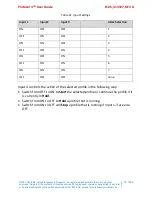
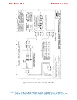
Page 74: ...run by external inputs wired to the controller from an external source such as a PLC or switches on a control panel Figure 29 displays standard digital input wiring Enable Digital Inputs through the P...

Page 75: ...er s personal use 75 of 82 Table 21 Input Settings Input 1 Input 2 Input 3 Index Selection ON OFF OFF 1 OFF ON OFF 2 ON ON OFF 3 OFF OFF ON 4 ON OFF ON 5 OFF ON ON 6 ON ON ON 7 OFF OFF OFF none Input...

Page 76: ...cooling of electronics components inside device Keep equipment accessible Do not permit other materials to be stored or piled against it Protect equipment against excessive heat Avoid temperatures gre...

Page 77: ...band and the soak timer has stopped Program a slower ramp rate or if oven is not heating check heater circuit Top PV displays OPEN Control thermocouple is disconnected or broken Repair or replace the...

Page 78: ...rchaser s personal use Baud Rate o For problems communicating try a lower baud rate But start with the default baud rate o Default 19 2K Parity o Leave parity at the default setting o Default None In...

Page 79: ...stered trademark in the U S and other countries No part of the contents of this manual may be reproduced copied or transmitted in any form or by any means without the written permission from ITW EAE u...

Page 80: ...is a registered trademark in the U S and other countries No part of the contents of this manual may be reproduced copied or transmitted in any form or by any means without the written permission from...

Page 81: ...s a registered trademark in the U S and other countries No part of the contents of this manual may be reproduced copied or transmitted in any form or by any means without the written permission from I...

Page 82: ...itions pdf 9 2 Part Lists Replacement part drawings latest revision may be found online at https www despatch com manuals html Find many parts for Despatch ovens online at http www despatch com parts...

Reviews: