background image

Page 14

Despatch/Watlow 1500 Control Instruction Manual

Profile Mode

This section of the manual provides details on programming
the Watlow 1500 in the Change Data (

CHG DATA

) mode,

the Change Parameters (

CHG PARA

) mode and Guarded

Access.  Refer to the Watlow 1500 manual for more details.

Change Data Mode

When the Watlow 

CHG DATA

 LED is lit, the processor is in

the change data mode.  While in this mode, the
programming steps can be entered into the processor.

There are three step types:

C

Set Point (SP)

C

Jump Loop (JL)

C

Wait (WT)

Halt Conditions

The Watlow 1500 can HALT in three ways, when the:

C

processor encounters a Blank Step in the program,

C

RUN/HALT

 key is pressed while the program is

running,

C

remote hold input is shorted.

While in the HALT condition, the Watlow 1500 actively
maintains set points and event output conditions which
existed at the time the processor was halted.

If you do not want the hot or humid conditions to be retained
at the end of a programmed halt, add a step just before the
Blank Step [End of Program] to establish stand-by set points
near ambient with all Event Outputs OFF.

Summary of Contents for Watlow 1500 Control

Page 1: ...P N 260786 Rev 8 96 E 87 U S 45 00 Instruction Manual for the Despatch Watlow 1500 Control...

Page 2: ...equipment could cause an explosion that may result in equipment damage personal injury or possible death Dear Customer Thank you for choosing Despatch Industries We appreciate the opportunity to work...

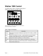
Page 3: ...packing installing operating and maintaining the control The APPENDIX section contains Special Instructions for operating the control instrument and a Troubleshooting Table An efficient way to learn a...

Page 4: ...Page ii Despatch Watlow 1500 Control Instruction Manual...

Page 5: ...rt 12 LPB Series Guarded Access Chart 13 Profile Mode 14 Change Data Mode 14 Halt Conditions 14 Blank Step 15 Set Point Step 15 Creating Files Profiles 16 Wait Steps 20 Next Step 21 Recycle Option 21...

Page 6: ...ure 2 DIP Switch Location and Orientation 36 List of Tables Table 1 Watlow 1500 Displays 4 Table 2 Watlow 1500 Keys 5 Table 3 Watlow 1500 LEDs 5 Table 4 GA0001 and 0002 PID Tuning Parameters 10 Table...

Page 7: ...dity from a variety of inputs The controller is easy to use Control functions alarm settings and other parameters are easily entered through the front keypad Limited data can be protected from unautho...

Page 8: ...Page 2 Despatch Watlow 1500 Control Instruction Manual...

Page 9: ...fans the following sequence will automatically take place 1 The controller will power up 2 The controller MNTR DATA LED will light up and the alarm indicator A1 will be flashing in the FUNCTION displa...

Page 10: ...Lowest significant event is left justified instead of right justified as when events are shown in data display Step Shows which step the programmer is currently pointed to Function Describes the funct...

Page 11: ...nge data and change parameter modes Increases and decreases the value in the DATA display A light touch changes the value by one Holding the key down causes the DATA display to increase rapidly Table...

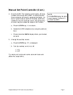
Page 12: ...ure a Press the FCTN key until C1 is signaled in the FUNCTION display b Update the dry bulb temperature by using up down arrow keys c Press enter when the desired set point is signaled in the data dis...

Page 13: ...mage If a dry air system and an electronic humidity sensor are installed in lieu of a wet bulb sensor the optional dry air event may be outside the range of 4EC to 98EC a Press the FCTN key C2 is show...

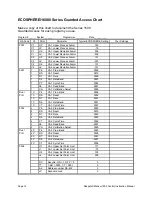
Page 14: ...wing GA 0000 To set CH 1 and CH 2 alarm limits GA 0001 To set CH 1 PID tune parameters GA 0002 To set CH 2 PID tune parameters GA 0006 To set set point scroll limits optional lockout and option recycl...

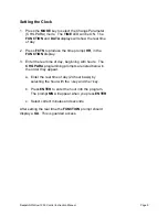
Page 15: ...HR in the FUNCTION display 3 Enter the real time of day beginning with hours The CHG PARA programming prompts are listed below in the order they appear a Enter the real time of day 24 hour basis by se...

Page 16: ...ameters Parameters FUNCTION Display Description Upper Process Type Alarm UP If you do not want this alarm set to highest value Lower Process Type Alarm LP If you do not want this alarm set to lowest v...

Page 17: ...0 to deactivate the recycle option Temp Temp 2 channel temperature control TT This prompt will not appear on thermocou ple units Select C 0000 for Temp RH control C 0001 or Temp Temp control RS 422 A...

Page 18: ...and 0009 1 RS Ch 1 Reset 0010 1 RT Ch 1 Rate 0000 1 Rb Ch 1 Rate Band 0001 1 CT Ch 1 Cycle Time 0003 1 db Ch 1 Dead Band 0001 1 CA Ch 1 Calibration Adjust 0000 Dual PID 1C Pb Ch 1 Prop Band 0009 1C RS...

Page 19: ...Lower Process Alarm 001 C2 Ud Ch 2 Upper Deviation Alarm 101 C2 Ld Ch 2 Lower Deviation Alarm 101 0005 RC Recycle 0000 C1 Pb Ch 1 Prop Band 0003 C1 RS Ch 1 Reset 0005 C1 RT Ch 1 Rate 0001 C1 Rb Ch 1...

Page 20: ...ssor There are three step types C Set Point SP C Jump Loop JL C Wait WT Halt Conditions The Watlow 1500 can HALT in three ways when the C processor encounters a Blank Step in the program C RUN HALT ke...

Page 21: ...t stop until reaching steps 47 51 required for cooldown and shutdown Set Point Step The existing start conditions for each step depend upon the programmed step previously performed by the Watlow 1500...

Page 22: ...s the FCTN key until SP appears in the function display 3 Press the ENTER key S1 will appear in the FUNCTION display and 0000 will appear in the DATA display 4 Use the FCTN key to select the variable...

Page 23: ...key and the key to enter the JS Jump Step parameter OR Use the FCTN key to advance to the next prompt without entering a value b Press the ENTER key c Use the key and the key to enter the JC Jump Coun...

Page 24: ...wait condition for the CH 1 set point can be entered b Use the key and the key to enter the wait condition OR Use the FCTN key to advance to the next prompt without entering a value c Press the ENTER...

Page 25: ...e 1 or 0 entry for Events 4 through 1 from left to right Press ENTER NOTE If you ve set DIP Switch 1 ON then there are only three events available for each channel In that case each Event 4 is an alar...

Page 26: ...H WM or WS is shown you could end up waiting for midnight when you wanted wait for time ignored 2 Table 8 Wait Steps Wait Steps The Wait WT submode allows the Watlow 1500 to wait for C Channel 1 and o...

Page 27: ...d information If there is data in the subsequent step the processor will move to the first prompt in that submode If you want a different step from NX select the number of the step you want in the DAT...

Page 28: ...ber of steps in the program may be as many as 51 We suggest that you write it out on copies of the charts in this section This will enable you to program the Series 1500 quickly and without mistakes T...

Page 29: ...Programming Work Sheet Name Date Step No Set Point Events Duration Comments CH 1 EC or EF S1 CH 2 or E S2 1 ON E1 4321 0 OFF E2 4321 HR MN SC 1 2 3 4 5 6 7 8 9 10 11 12 13 14 15 16 17 18 19 20 21 22 2...

Page 30: ...mpression 16 Blank step 17 18 19 20 130 10 Ramp C1 to 130EC 1EC min first not RH 21 85 05 Ram RH after temperature has been reached 22 W2 84 Wait for near set conditions 23 0000 00 30 Hold for 30 min...

Page 31: ...isplayed use arrow keys to 70 press enter E1 is displayed use arrow keys to 0000 press enter E2 is displayed use arrow keys to 0001 press enter HR is displayed use arrow keys to 00 press enter MN is d...

Page 32: ...until SC is displayed use arrow keys to 01 press enter TIME is displayed NX is displayed use arrow keys to 0005 press enter 11 At Step 5 the display will read 05 SP press enter S1 is displayed use arr...

Page 33: ...er 14 At Step 8 the display will read 08 SP press enter S1 is displayed use arrow keys to 120 press enter S2 is displayed use arrow keys to 59 press enter E1 is displayed press FCTN E2 is displayed us...

Page 34: ...is displayed NX is displayed use arrow keys to 0011 press enter 17 At Step 11 the display will read 11 SP press FCTN until WT appears press enter Press FCTN until W2 is displayed use arrow keys to 008...

Page 35: ...ss enter JC is displayed use arrow keys to 0001 press enter Press FCTN until NX is displayed use arrow keys to 0015 press enter 21 At Step 15 the display will read 15 SP Press FCTN until JL appears pr...

Page 36: ...ress FCTN SC is displayed use arrow keys to 01 press enter TIME is displayed NX is displayed use arrow keys to 0050 press enter 25 At Step 50 the display will read 50 SP press FCTN until WT appears pr...

Page 37: ...noid 0 Open 1 Closed Drain Solenoid 0 Closed 1 Open HAST Chamber Programming Instructions and Definitions C1 Channel 1 Temperature EC C2 Channel 2 Relative Humidity RH SP Set Points S1 Set Temperature...

Page 38: ...ld for 30 minutes 6 S1 is changed to 10EC This is ramped over a 1 second period so it is essentially a step change Note Event 1 1 is turned off To protect the equipment humidity control generally need...

Page 39: ...0 30 00 Ramp to 25EC in 30 minutes 5 00 30 00 Hold 25EC for 30 minutes 6 10 0001 00 00 01 Step Ramp to 10 Humid event OFF 7 W1 8 Wait for 8EC ALL OTHER W S BLANK 8 00 30 00 Hold 10 for 30 minutes 9 JS...

Page 40: ...Program To clear an entire program perform the following steps 1 Press MODE key until CHG PARA LED lights 2 Press FCTN key until GA shows in FUNCTION display 3 Press the key until DATA display shows 0...

Page 41: ...wer Deviation Alarm 0001 1H Pb Ch 1 Prop Band 1H RS Ch 1 Reset 1H RT Ch 1 Rate 1H Rb Ch 1 Rate Band 1H CT Ch 1 Cycle Time 1 db Ch 1 Dead Band 1 CA Ch 1 Calibration Adjust Dual PID 1C Pb Ch 1 Prop Band...

Page 42: ...emory 2 A Cold start is a Clean startup condition All MEMORY IS DELETED and the controller will return to default settings 3 Upon completion of Cold start return the control to Warm start otherwise th...

Page 43: ...ry use only Must be in the ON position 6 Cold start on power up Memory cleared parameters set to default values Warm start on power up Programmed values are retained for all parameters 7 EC function a...

Reviews: