background image


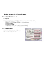
Before installing the software, you may want to turn off virus protection 
as it will significantly increase the amount of time it takes to install the 
software. 

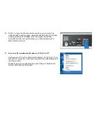
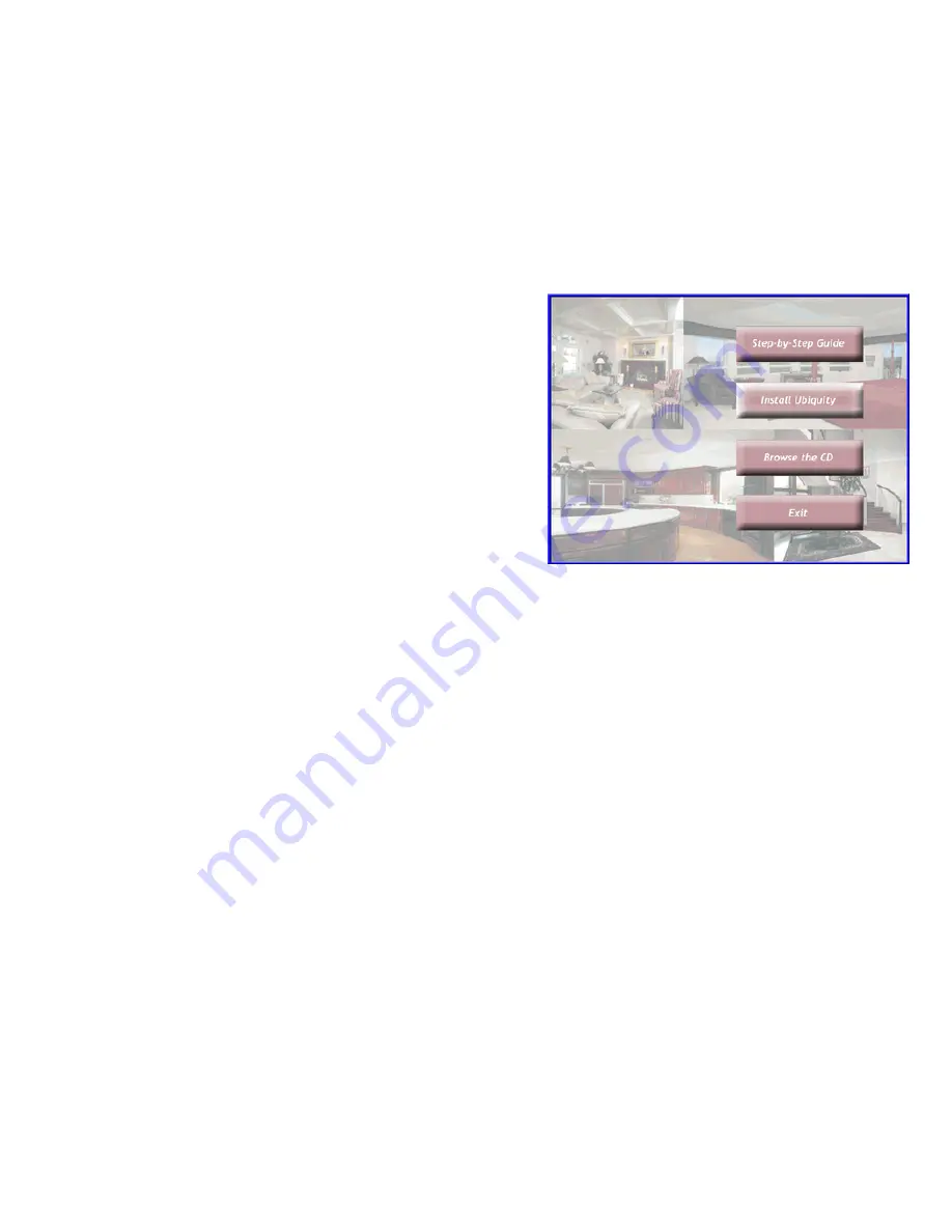
The next step will be to click the "Install Ubiquity" button on the start 
up screen to install the software on your PC. You will probably want to 
select all of the defaults by clicking "Next" at each screen.  

While it is installing, you may want to see the rest of the contents of 
the CD by clicking the "Browse the CD" button.  

After you have installed the software, close the start up pop up menu 
by clicking the "Exit" button

Please go on to the next step while the software is still installing.. 


Summary of Contents for Domain 3000

Page 1: ...Select Tools Windows update This will take you to a Microsoft web page 3 Click Scan for Updates 4 Install all Critical Updates 5 Repeat the process it may take a few times to install all critical upda...

Page 2: ...the start up screen to install the software on your PC You will probably want to select all of the defaults by clicking Next at each screen While it is installing you may want to see the rest of the c...

Page 3: ...f cardboard with a small hole in the middle of it Place the cardboard against the front of the AV component and move the hole around the front while sending IR commands to the AV component via the rem...

Page 4: ...omfortable with IP networking you can connect both your PC and the Domain 3000 to your network and skip the next set of steps Connect your PC directly to the Domain 3000 with an Ethernet crossover cab...

Page 5: ...Controller is either not communicating or is communicating at 10 Mbps Neither will work Give Your PC an Alternate IP address of 172 16 16 117 Configure your PC with an Alternate IP address of 172 16 1...

Page 6: ...etwork Connections menu make sure your wireless network is disabled right click it and select Disable if necessary Then in the same Network Connections menu right click on the Ethernet port that is pl...

Page 7: ...The Local Area Connection Properties menu will pop up On the Local Area Connection Properties menu select Internet Protocol TCP IP and click the Properties button...

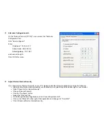
Page 8: ...onfiguration tab On the Internet Protocol TCP IP menu typically it will try to Obtain an IP address automatically and look like the menu at the right If this is the case you can proceed to the next st...

Page 9: ...bnet mask 255 255 0 0 Default gateway 172 16 0 1 the rest will not matter If your PC was on the 192 168 x x network or the 10 x x x or any other network than the 172 16 x x network then it is likely t...

Page 10: ...nternet Security on your PC please enable the Ubiquity application by doing the following Right click the Norton Internet Security icon located in your system tray at the bottom right or your screen S...

Page 11: ...k is behaving properly The right section of the application will show you information about the Domain Controller and its connection to the network when the name of a Domain 3000 appears in the box on...

Page 12: ...Now skip over the other method of using a Local Area Network to connect to the Domain 3000 and go to opening the Design Module...

Page 13: ...le that should only be used to connect your PC directly to the Domain 3000 Connect your PC to the same Ethernet switch Note that your PC can be connected to some other point in the network or even via...

Page 14: ...at Internet connectivity is not necessary for using Destiny Networks products If you have Internet access from your PC you will get a green OK if not then this test will show a red Not Available Again...

Page 15: ...172 16 16 116 then it did not receive an IP address via DHCP and is using its default IP address To configure a static IP address click the Name IP Settings button near the bottom left of the Find My...

Page 16: ......

Page 17: ...ts in your theater and tell how they are physically wired The Ubiquity software will do the rest The Design Module consists of a number of layers that can be selected by clicking one of the buttons on...

Page 18: ...se Emitter Alternatively you can use RS 232 connections AV components that only have toggle on off commands require an additional connection The Domain Controller always wants to know whether an AV co...

Page 19: ...mposite video cable gets connected to 3 pin Phoenix connector as described in Video Sync Digital Inputs One very important consideration is to make sure that the composite signal is available when the...

Page 20: ...other components as shown below Add the IR and serial control cables to your block diagram and indicate what port on the Domain controller they will use If you know that some of the AV components do...

Page 21: ......

Page 22: ...teps to configuring AV equipment Add the Components Wire them together Add the Components Select the AV Entertainment layer of the Design Module Click anywhere in the room in which you plan to have AV...

Page 23: ...ee all of the AV components throughout the house Use this view to connect AV and control wires to distributed audio and video components Once you are in the Whole House view you will not be able to ad...

Page 24: ......

Page 25: ...ers AV switches are of the Switch type 3 Choose the Manufacturer 4 And the Model 5 Each model may have one or more files associated with it Usually the file name gives some indication to the completen...

Page 26: ...en click the Add Continue button It will add the selected AV component and keep this menu open to add more AV components to the project 10 If this is the last AV component you want to add to the proje...

Page 27: ...nt does not exist in the library please check the AV components on our web site to see if the component has been added more recently than those shipped with this software release If not please proceed...

Page 28: ...Clicking ignore will cause AV AWARE to ignore this error Clicking more will give you the long version of the error message and point you to possible solutions...

Page 29: ......

Page 30: ...select HD DVR You can use the defaults for the rest Click Add Continue Add the Denon AVR 3805 Surround Receiver Select the AV Surround Receiver Type Denon for the Manufacturer And the AVR 3805 Model C...

Page 31: ...d your favorite 5 1 surround sound speakers Select the Speaker Type Generic for the Manufacturer And the Surround 5 1 speakers Model You can use the defaults for the rest Click Add because we are fini...

Page 32: ...ck on the x at the far right of this line The top set of ports will be outputs and they will be right justified The 2nd set of ports will be inputs and they will be left justified The 3rd set of ports...

Page 33: ...Red IR Control Yellow Power Sense Silver Serial...

Page 34: ......

Page 35: ...on wire types please see Wires for Video and Wires for Audio Auto Wire will not wire the following device types Amplifiers Splitters and Video Processors Also it will not wire distributed AV to multip...

Page 36: ...o it will not wire S Video Note that the Line 5 1 Speakers output from a DVD player to an AV surround receiver will be wired but that those wires do not count as the audio wire That is the 5 1 can be...

Page 37: ...you to do the assignment in the AV surround receiver The software cannot do that assignment for you Make a note of the assignments perhaps using a screen capture and print program like PrintKey2000 T...

Page 38: ......

Page 39: ...Note that errors still exist If you click on the err of both components you will get the following...

Page 40: ......

Page 41: ...ire then you will want to do the following Let s start at the far right Click on the port at the top of the Living room TV It is named Cpt 1 Component That port will turn blue and all compatible outpu...

Page 42: ......

Page 43: ...e will be drawn between the two ports that were selected Now the Ubiquity software running in the Domain Controller now knows that a path exists from the Component output of the Denon AV surround rece...

Page 44: ......

Page 45: ...already have a connection going to them If you choose to wire to an orange port you will be told that your are deleting an existing connection To see the orange highlighting click on the 2nd port of t...

Page 46: ......

Page 47: ...port of the Living room projector TV as shown in blue in the upper right of the schematic below Two serial ports belonging to the Domain 3000 turn colors For our example click on the second serial po...

Page 48: ......

Page 49: ...the serial port of the Living room projector TV as shown below Note that the Ubiquity software now knows how to turn the power of the projector TV on and off and how to select the appropriate input c...

Page 50: ......

Page 51: ...Speakers output of the Denon will turn green as shown below indicating that you can connect a 7 speaker output to a 5 speaker input In general you can hook up outputs of a greater number of speakers t...

Page 52: ......

Page 53: ...ant you can add the wire from the line subwoofer of the Denon to the speakers It won t make any difference whether this line is added as the control commands issued by the Domain 3000 will not change...

Page 54: ......

Page 55: ...Subwoofer wire added below...

Page 56: ......

Page 57: ...u click on either port that a wire is connected to both ports will become highlighted in red and the wire will be outlined in blue as shown below Note also as it says at the top of the menu that if yo...

Page 58: ......

Page 59: ...x Digital Two assignable coax digital inputs will turn green Note that these ports are not presently assigned to any of the inputs of the AV receiver This assignment will happen in the next step Click...

Page 60: ......

Page 61: ...er to the coax input of the AV surround receiver Note that the Domain controller will not program the Denon AVR 3805 to assign the Coax Digital input to the DVD input connector group Rather you are ju...

Page 62: ......

Page 63: ...u will want to open the Device Description Wizard to fix it Wire the DVD Player s Component Video Output Select the Component output port of the DVD player as shown below in blue Note that there are 5...

Page 64: ......

Page 65: ...n The component output of the DVD will be connected to the component input of the DVD input connector group of the Denon Now the Ubiquity software knows of a path from the DVD player through the Denon...

Page 66: ......

Page 67: ...e Domain 3000 become highlighted in green indicating that they are available to control the DVD player note that even after an IR port is assigned to control one AV component it will still light up in...

Page 68: ......

Page 69: ...Click on IR Out Port 1 of the Domain 3000 to wire that port to control the DVD player You will get the schematic shown below Note that IR wires show up in red...

Page 70: ......

Page 71: ...t the power status of this device in another way In this case we will assume that we can use the composite output signal of the DVD player to indicate that it is on but be careful as it is unlikely th...

Page 72: ......

Page 73: ...sary to the DVD player Click on the IR Control port of the Denon AV surround receiver Connect it to IR Out Port 3 of the Domain 3000 You should end up with the schematic shown below Now the Ubiquity s...

Page 74: ......

Page 75: ...button Select File Open browser GUI from the dropdown menus in the upper left This will open the Browser GUI pointing to the simulator if you are working off line or to the Domain Controller if you a...

Page 76: ...Open the Entertainment Browser GUI Click on the Entertainment icon to open the Browser GUI Entertainment menu...

Page 77: ...ft It populates the buttons based on which AV sources can get to the projector TV display and speakers Note that DVD player can be an audio only source when it plays CDs If you select this button the...

Page 78: ...button is defined in the Device Description File of the source that is playing at this point in time in our case the DVD player Wire the PVR Return to the Design Module Open the Schematic by clicking...

Page 79: ...to the Video Sync Input 2 port of the Domain 3000 High when On The schematic should look like the one below Note that the Ubiquity software now knows how to set up a path from the PVR to the Living ro...

Page 80: ......

Page 81: ...the Entertainment Browser GUI You must re generate the Entertainment Browser GUI menu to update the menu with the PVR that was just added to the Design Module Click on the Entertainment icon as shown...

Page 82: ...You should get the menu at the right Note that the PVR button has been added to the menu but the DVD is still playing Click the PVR button if you like to see the controls for it...

Page 83: ...ng dropdown screens and plasma lifts Every AV component can activate a relay or a voltage trigger when it turns on To get access to the relay we need to bring up the Info menu for the Living room proj...

Page 84: ...wever at present it is part of this project and may be different than the ones you have in your library if your library was changed after adding this description file to this project Edit this Device...

Page 85: ...as Needed There s a check box to turn the power on and off as needed If you wanted to just leave the AV component on all of the time uncheck this check box Energize a Relay At the bottom there is a c...

Page 86: ...lled Energize a relay Now you need to associate this with an actual relay To do that click on the Energize a relay port to select it You will get the schematic shown below where the possible relays an...

Page 87: ......

Page 88: ...he Domain 3000 sends a command to the projector TV to turn it on the Domain 3000 will also energize 12V trig 1 of the Domain 3000 to go high The 12V trigger will stay high until the Domain 3000 sends...

Page 89: ......

Page 90: ...a plotter you do not have much control of the formatting To get much greater control you can print it to Adobe Acrobat provided you have the paid for application In order to have access to the larger...

Page 91: ...Right click on Adobe PDF and select Set as Default Printer From the File drop down menu select Print...

Page 92: ...e as your default printer you will be able to select A3 as the paper size This will give you a much larger page Also set all 4 margins to zero 0 As shown at the right it may not give you exactly zero...

Page 93: ...The Adobe application will open if it was not already open and you will see the menu at the right Click OK...

Page 94: ...ave PDF File As menu will appear Navigate to c Program Files Destiny Networks Projects and into a folder for this particular project if you have one Use the default name or give it another name Click...

Page 95: ...Acrobat will now have the schematic Click File Print...

Page 96: ...real printer you want to use to print with Select Fit to paper for the Page Scaling Click OK and you will have the schematic on one page When you are finished printing do not forget to reset your defa...

Page 97: ...ys Watching And Reporting Errors There are 2 was to get to Check My Destiny From Find My Destiny and from the Browser GUI From Find My Destiny Make sure the Domain 3000 is selected on the right hand s...

Page 98: ...s sign on the left of a line means that the line can be expanded further by clicking on the plus sign or even to the right of it on the same line The minus sign means that it has already been expanded...

Page 99: ...tus will not show up immediately Entertainment Expand the Entertainment Theater and Theater line items by clicking on the signs Then click on Show last 20 cmds to see the display below Every new event...

Page 100: ...ith the time at which they execute relative to what cause the event Finally there is a solid line indicating the event is over Note that this information is cycle accurate give or take a few tens of m...

Page 101: ...systems in that it includes the most common sources For example it includes our two sources the DVD player 2nd button down in the 2nd column and the PVR 3rd button down in the 1st column so all we nee...

Page 102: ......

Page 103: ...Save the project on the Domain 3000 Select File Save from the dropdown menu Save a backup copy to your PC Go to the Design Module Select File Save as from the dropdown menu...

Page 104: ...formation as shown in the lower image at the right After a short while this menu will go away and the main design area of the Design Module will turn blue with a message on it that says it is uploadin...

Page 105: ...VD players MP3 players Tuners etc have buttons assigned to them AV Surround Processors Switches Video Processors Speakers and TVs a k a displays and projectors do not get buttons assigned to them If y...

Page 106: ...e window to make it easier to view It will list the commands it took to set up the path from the source to the display and or speakers 9 At this point you have identified that the software tried to se...

Page 107: ...s or Video Digital Inputs as appropriate Expand the List of Commands Use the remote control that came with the AV component to turn the power on and off If the change in status does not appear on Chec...

Page 108: ...t with its power on off button If it does not work check the wiring and software configuration It must work before proceeding To see the value that sensing the power status provides for you Turn off a...

Page 109: ...tead of a straight through cable or vice versa Try adding a Null modem to the cable The cable is broken Try a known good cable Hyper Terminal is connected via the wrong COM port Try the other availabl...

Page 110: ...le Make sure the RC 1 remote control has new batteries installed in it The batteries last about 4 months Open Check My Destiny by expanding the RF and IR Inputs section as shown at the right Expand th...

Page 111: ...test the reception of the RF remote You will find 2 limitations There will be a distance limitation and there will be null spots where multi path distortion prevents the signal from being detected Th...

Reviews: