background image

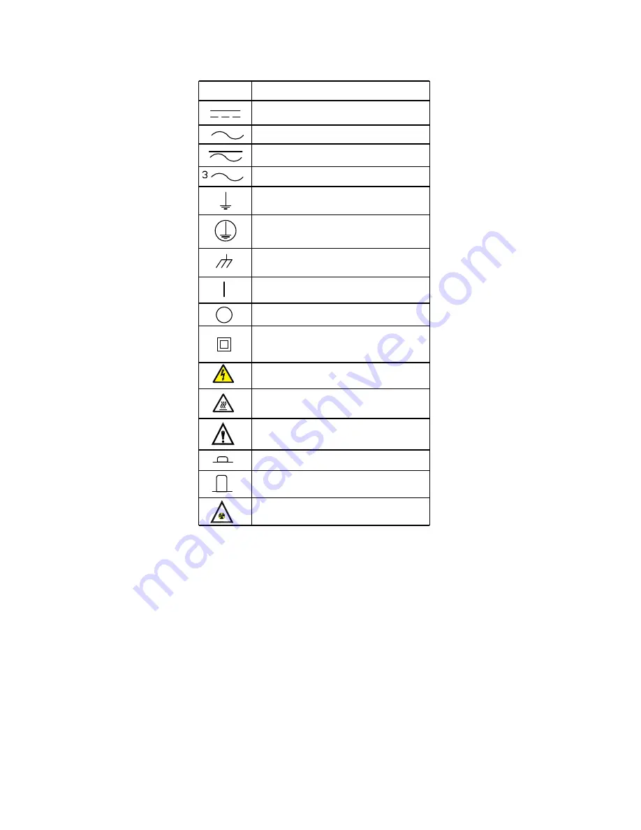
EQUIPMENT SAFETY SYMBOLS

Direct current

Alternating current

Both direct and alternating current

Three-phase alternating current

Earth (ground) current

Protective conductor terminal

Frame or chassis terminal

On (power)

Off (power)

Equipment protected throughout 

by double insulation or reinforced 

insulation

Caution, possibility of electric shock

Caution, hot surface

Caution*

In position of bi-stable push control

Out position of bi-stable push control 

Ionizing radiation

Symbol

Description

* Manufacturer to state that documentation must be 

consulted in all cases where this symbol is marked.

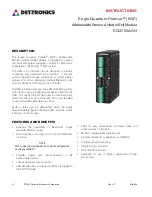
Summary of Contents for Eagle Quantum Premier EQ3750ASH

Page 1: ...5 1 Rev 4 17 95 8654 Instructions Eagle Quantum Premier Addressable Smoke Heat ASH Module Model EQ3750ASH...

Page 2: ...s the EQP Controller to annunciate a fire alarm from either its own LON based I O or from the ASH connected addressable detection loops System status can be determined using the Eagle Quantum Safety S...

Page 3: ...SLCs the ASH Module supports Class A Class B and Class X SLC wiring styles NOTE A maximum of sixty five isolators may be used on the Apollo loop For the Class A wiring style isolators are optional on...

Page 4: ...dule and Priority Mini Switch Monitor P N 55000 765 Priority Switch Monitor P N 55000 806 Input Output Module P N 55000 820 and Sound Control Module P N 55000 825 must be no longer than 20 ft 6 m and...

Page 5: ...58000 600 Apollo Optical Smoke Detector EU 000515 503 58000 400 Apollo Heat Detector EU 000515 504 58000 700 Apollo Multisensor EU 000515 505 58000 300 Apollo Carbon Monoxide Detector EU 000515 507 4...

Page 6: ...rity check requests are ignored during an AIC and if a manual integrity check is in progress when an AIC is scheduled the AIC will be delayed Manual Integrity Check MIC The manual integrity check can...

Page 7: ...use field wiring suitable for both minimum and maximum ambient temperatures The screw terminals are to be tightened with a minimum torque of 0 5 Nm IECEx ULD 10 0004X Ex nA nC IIC T4 Gc Tamb 40 C to 8...

Page 8: ...t response mode The start and stop times are then set according to the desired switchover time At the start time the response mode is set to the Day Mode Start Time setting At the stop time the respon...

Page 9: ...ement describing the malfunction must accompany the returned device or component to assist and expedite finding the root cause of the failure Pack the unit properly Always use sufficient packaging mat...

Page 10: ...ssis terminal On power Off power Equipment protected throughout by double insulation or reinforced insulation Caution possibility of electric shock Caution hot surface Caution In position of bi stable...

Page 11: ...e 6901 West 110th Street Minneapolis MN 55438 USA www det tronics com Phone 1 952 941 6665 Toll free 1 800 765 3473 Fax 952 829 8750 det tronics carrier com Specifications subject to change without no...

Reviews: