background image

INSTRUCTIONS

Eagle Quantum Premier

® 

(EQP)

Addressable Smoke Module (ASM) 

 EQ3760ASM

1.3

 ©

Detector Electronics Corporation 2017 

Rev: 9/16 

95-8755

DESCRIPTION

The Eagle Quantum Premier

®

 (EQP) Addressable Smoke 

Module (ASM) is designed to expand the input and 

output capability of Detector Electronics Corporation’s 

(Det-Tronics

®

) EQP system.

The ASM is a SIL2 certified interface device designed 

to provide continuous and automated fire protection. It 

ensures system operation through supervision of system 

inputs/outputs and Local Operating Network/Signaling 

Line Circuit (LON/SLC) monitoring in the controller.

The ASM is located directly on the LON of the EQP 

system, with a loop of up to 100 addressable devices 

connected to the ASM. This allows the EQP controller to 

annunciate a fire alarm from either its own LON based I/O 

or from the ASM connected addressable detection loops.

System status can be determined using the Eagle 

Quantum Safety System Software (S

Version: 10.15.0.5 

or later), and the status indicators on the module.

FEATURES AND BENEFITS

•  Expands the capabilities of Det-Tronics’ Eagle 

Quantum Premier system

•  EQP Controller can support up to 10 ASM Modules 

on a loop

NOTE

This support is dependant on system configuration 
and logic within S

3

.

•  Provides power and communications to 100 

addressable devices

•  Utilizes Apollo Discovery devices
•  XP95 protocol/devices supported

•  ASM Module alarm and fault conditions are logged in 

the EQP Controller

•  LEDs for easy annunciation of power, faults and 

active devices on the loop

•  Monitors single addressable devices
•  Provides remote I/O capabilities via LON/SLC
•  DIN rail or panel mounting
•  Plug-in wiring connectors
•  RFI and EMI hardened
•  Approved for use in marine applications (Panel 

mount only)

•  SIL2 when using SIL rated smoke detectors
•  Provides intrinsic safety smoke detector option

Summary of Contents for Eagle Quantum Premier EQ3760ASM

Page 1: ... O or from the ASM connected addressable detection loops System status can be determined using the Eagle Quantum Safety System Software S3 Version 10 15 0 5 or later and the status indicators on the module FEATURES AND BENEFITS Expands the capabilities of Det Tronics Eagle Quantum Premier system EQP Controller can support up to 10 ASM Modules on a loop NOTE This support is dependant on system conf...

Page 2: ...C wiring styles NOTE A maximum of 101 isolators may be used on the Apollo loop For the Class A wiring style isolators are optional on the ASM Module Apollo loop where only a single zone is monitored During a single open a single ground fault or the combination of a single open and a single ground fault the Class A pathway shall maintain alarm receipt capabilities See Figure 2 for Class A pathway C...

Page 3: ...odule and Priority Mini Switch Monitor P N 55000 765 Priority Switch Monitor P N 55000 806 Input Output Module P N 55000 820 and Sound Control Module P N 55000 825 must be no longer than 20 ft 6 m and must be installed in conduit or equivalently protected against mechanical injury For additional information and documentation regarding all Apollo devices visit www apollo fire co uk A2713 ASM MODULE...

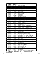
Page 4: ...ollo Manual Call Standard Non Isolated Waterproof EU 000515 XXX 58200 971MAR Apollo Manual Call Standard Isolated Waterproof Marine 000515 XXX 58100 908SIL Apollo Manual Call Standard Isolated Non Waterproof SIL2 000116 180 53832 070 Apollo Remote Led 1 Gang Red 000515 510 55000 852 Apollo Sounder Control Unit 000515 515 55000 278 Apollo Sounder 100dB Red 000515 518 55000 293 Apollo Sounder Beacon...

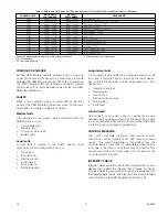
Page 5: ... control The control message is transmitted from the controller every 20 seconds or immediately when there is a change in the state of an output channel A fault will be annunciated if the control message is not received at the controller within 2 minutes INTEGRITY CHECK Integrity checks are internal tests that are performed on loop devices that support the integrity check feature All Apollo Discov...

Page 6: ... AIC or MIC will be ignored Integrity Check Faults When an integrity check fails the loop device fault LED will be activated The fault indication will remain until an ASM Module reset is performed or until another integrity check is done and passes NOTE If there is an active alarm any new integrity check request is ignored If an integrity check is in progress and an alarm condition occurs the inte...

Page 7: ...The screw terminals are to be tightened with a minimum torque of 0 5 Nm IECEx ULD 10 0004X Ex nA nC IIC T4 Gc Tamb 40 C to 85 C Compliance with IEC 60079 0 2011 IEC 60079 15 2010 The ASM Module can not be used for applications that fall within the scope of the CPR directive INSTALLATION All electrical connections are made to the field wiring connectors furnished with the module Refer to Figure 7 f...

Page 8: ...tchover time At the start time the response mode is set to the Day Mode Start Time setting At the stop time the response mode is set to the Day Mode Stop Time setting If the day response mode value is set equal to the night response mode the day night mode functionality is effectively disabled The default value for the start time is 8 00 AM and 10 00 PM for the stop time The start and stop times a...

Page 9: ...ffice so that the Return Material Identification RMI number can be assigned A written statement describing the malfunction must accompany the returned device or component to assist and expedite finding the root cause of the failure Pack the unit properly Always use sufficient packaging material Where applicable use an antistatic bag as protection from electrostatic discharge NOTE Det Tronics reser...

Page 10: ...e the available energy in a hazardous area and contravene the energy limitations of the I S Certification All XP95 I S circuits must therefore be connected as spurs from the safe area loop or as radial connections from the control panel It is recommended for the highest system integrity that each I S circuit be restricted to a single zone and that the connection from the safe area loop to the I S ...

Page 11: ...assis terminal On power Off power Equipment protected throughout by double insulation or reinforced insulation Caution possibility of electric shock Caution hot surface Caution In position of bi stable push control Out position of bi stable push control Ionizing radiation Symbol Description Manufacturer to state that documentation must be consulted in all cases where this symbol is marked ...

Page 12: ...ty System Corporate Office 6901 West 110th Street Minneapolis MN 55438 USA www det tronics com All trademarks are the property of their respective owners 2017 Detector Electronics Corporation All rights reserved Det Tronics manufacturing system is certified to ISO 9001 the world s most recognized quality management standard Phone 952 946 6491 Toll free 800 765 3473 Fax 952 829 8750 det tronics det...

Reviews: