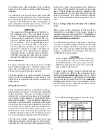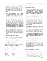
The shorting plug, which attaches to the connector
board, must be in place at all times that the sensor is
operating.
The calibration cup can remain on the sensor after
calibration without interfering with normal operation.
By connecting a length of tubing from the calibration
cup back to the transmitter location, the operator can
make calibration adjustments and also control the
flow of calibration gas from the same location.
IMPORTANT
The operator must frequently inspect the filter on
the calibration cup. This filter must be kept
clean. If the filter should become clogged by
environmental contaminants such as dirt, oil,
paint, etc., the flow of gas to the sensing element
will be restricted. This can significantly reduce
the sensitivity and response time of the sensor,
thereby impairing the ability of the system to
respond to a hazardous condition. Problems of
this nature will not be detected by the system’s
diagnostic circuitry or during routine calibration.
If the filter becomes dirty and cannot be properly
cleaned, the calibration cup must be replaced.
Sensor Installation
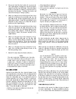
For proper operation, the sensor must be oriented
with the filter pointing down. Install the sensor in the
lower 3/4 inch NPT opening on the junction box.
Connect the conduit to the upper opening.
The sensor junction box can be mounted to a wall or
post, or it can be suspended by the conduit. The
junction boxes should be electrically connected to
earth ground.
Wiring Requirements
Three wire cable is used for connecting the sensor to
the transmitter and also for connecting the transmitter
to the controller. The use of shielded cable is
required for connecting the sensor and transmitter,
and is highly recommended for connecting the trans-
mitter and controller.
Three conductor cable with a
foil shield is recommended. The shield of the cable
connecting the sensor and transmitter should be
open at the sensor junction box and connected to
earth ground at the transmitter junction box. The
shield of the cable connecting the transmitter and
controller should be open at the transmitter junction
box and connected to earth ground at the controller.
The maximum distance between the sensor and
transmitter is limited by the resistance of the connect-
ing wiring, which is a function of the gauge of the wire
being used. Note that maximum wiring distances
also vary with the specific transmitter model being
used. Table 4 shows the maximum separation dis-
tance allowed for a given wire size when using K
Series Transmitters. For other transmitter models,
refer to the transmitter manual for specific instruc-
tions.
Sensor Voltage Adjustment (K Series Transmitters
only)
When using a sensor separation kit with a K Series
Transmitter, an adjustment to the sensor voltage is
required to assure proper operation. This adjustment
should be performed at the time of system startup,
before calibration is performed.
The combustible gas sensor is designed to operate at
3.3 volts dc. Greater voltages will shorten sensor life
and lower voltages will reduce sensitivity to certain
gases. The sensor supply voltage is factory adjusted.
However, re-adjustment is necessary if the sensor
and transmitter are separated.
CAUTION
Sensor voltage adjustment requires the removal
of the junction box cover at both the sensor and
transmitter locations. The area must be de-clas-
sified when removing the junction box cover with
power applied to the system.
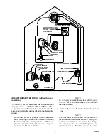
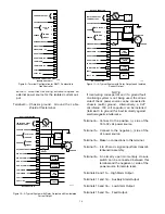
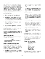
To adjust sensor voltage, connect a digital voltmeter
WHT and –BLK on the connector board
inside the
sensor junction box
(see Figure 5). Install
the transmitter extender plug between the transmitter
module and the connector board in the
transmitter
junction box
to allow access to potentiometer R18 on
the transmitter module. Adjust R18 to obtain a read-
ing of 3.3 volts on the voltmeter.
10
Table 4—Maximum Separation Distances – Sensor to K Series
Transmitter
Shielded
Recommended Maximum
Wire Size
Transmitter to
(AWG)
Sensor Distance*
Feet
Meters
18
50
15
16
75
23
14
125
38
*Sensor voltage adjustment is required.


