background image

Instructions 95-8410

 Carbon Monoxide Controller
R8471E

2.1 8/07 

95-8410

Summary of Contents for R8471E

Page 1: ...Instructions 95 8410 Carbon Monoxide Controller R8471E 2 1 8 07 95 8410...

Page 2: ...Programming 14 INSTALLATION CHECKLIST 15 Section III System Startup STARTUP PROCEDURE 15 SETPOINT ADJUSTMENT 16 Setpoint Display Mode 16 Setpoint Adjustment Procedure 16 CALIBRATION 17 Calibration Pr...

Page 3: ...a 4 to 20 ma input Digital display bar graph display and high intensity LEDs indicate important system status information AutoCal feature provides easy and accurate calibra tion Microprocessor based c...

Page 4: ...8471E Controller base and premium model in 3U and 4U height has been tested and approved by FMA It can be used with any FMA approved sens ing device capable of generating a 4 to 20 ma input FMA approv...

Page 5: ...when exposed to various commonly encountered substances CONTROLLER Faceplate Description The controller faceplate provides LEDs for identifying system status conditions a digital display and a bar gra...

Page 6: ...ashes upon detection of a system fault and is on steady during the power up time delay 8 RESET Pushbutton Used for various system programming and calibration functions as well as for resetting the con...

Page 7: ...ys are also switch programmable for either normally energized or normally de energized operation programmable as a group only not individually The fault relay is normally energized The low and auxilia...

Page 8: ...WER UP TIME DELAY When power is applied to the controller it enters a time delay mode to allow the sensor output to stabilize before beginning normal operation During this time the outputs are inhibit...

Page 9: ...ed When the signal decreases below the high alarm set point The high alarm is always latching and unaffected by the latching non latching programming for the low and auxiliary alarms High LED is on st...

Page 10: ...utput goes to a preset level adjustable from 0 to 20 ma with a default value of 4 0 ma SENSOR REPLACEMENT This mode inhibits all controller outputs to allow replacement of the sensor cell without remo...

Page 11: ...nce caused by extraneous electrical noise In applications where the wiring cable is installed in conduit the conduit must not be used for wiring to other electrical equipment Since moisture can be det...

Page 12: ...lly plug it into the sensor base NOTE Handle the sensor cell carefully To avoid possible damage observe the normally accepted procedures for handling electrostatic sensitive devices See form 75 1005 f...

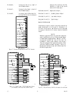
Page 13: ...ation in a non haz ardous area Figure 11 shows the terminal configuration for the R8471E CO Controller Terminals 1 and 2 4 to 20 ma dc output Non Isolated Current Output If the 4 to 20 ma current loop...

Page 14: ...N LINE WITH THE CLIP IN THE BOTTOM BRACKET 3 GAS CONTROLLERS ARE APPROX ONE INCH WIDE AND REQUIRE ONE RAIL FOR INSERTION PLACE CLIPS IN LINE WITH GUIDE RAILS CAGES WILL ACCEPT AS MANY GAS CONTROLLERS...

Page 15: ...sient suppression Figure 12 A Typical System R8471E with Relay Outputs Non Isolated Current Output and C7066E Sensor CURRENT OUTPUT CHASSIS GROUND POWER SENSOR EXTERNAL RESET HIGH ALARM HIGH ALARM OC...

Page 16: ...acing a jumper plug on the appropriate pair of pins Each relay has a set of three pins For normally open operation place the plug on the NO and center pins For normally closed operation place it on th...

Page 17: ...re complete and have been performed correctly 1 Junction boxes are mounted securely and sen sors are pointing down 2 All cable shields are properly grounded 3 All junction box covers are tightly insta...

Page 18: ...as concen tration 5 After displaying the calibration gas concentra tion for two seconds the controller automatically leaves the Setpoint Display mode and returns to the Normal operating mode 6 If adju...

Page 19: ...ly pro grammed for the ppm concentration being used for calibration See the Setpoint Adjustment section Reprogram the controller if required Failure to do so will greatly impair system response 2 Be s...

Page 20: ...ondi tions Section IV System Maintenance ROUTINE MAINTENANCE To ensure reliable protection it is important to check and calibrate the CO detection system on a regularly scheduled basis The frequency o...

Page 21: ...cedure the controller will automatically return to the Normal mode when power is restored after a time delay To prevent the possibility of alarms allow the system to warm up in the sensor replacement...

Page 22: ...r wiring F97 Status 1 Controller type invalid Error in data from RAM Return controller to factory for repair F70 Status 1 External reset activated for over 15 seconds Check external switch and wiring...

Page 23: ...trollers only 4U racks can house gas or flame controllers in any combination See Figures 9 and 10 Rack sizes to accommodate 2 4 6 8 12 or 16 gas controllers are available Flame controllers require two...

Page 24: ...95 8410 2 1 22 Recommended Test Form Detector Detector Date Date Date Number Location Installed Checked Calibrated Remarks...

Page 25: ...95 8410 2 1 23 Fault Record Sheet Date Time Detector System Status Operator Comments Affected...

Page 26: ...IR Combustible Gas Detector Eagle Quantum Premier Safety System Eagle Logic Solver Safety System Det Tronics the DET TRONICS logo Eagle Quantum Premier and Eclipse are registered trademarks or tradema...

Reviews: