background image

Model 610-N4X-SA

the latching position and alarm conditions have passed.  Each Model 10 controller also has its own discrete 
alarm reset switch, which is discussed further in the Model 10 Instruction Manual. 

2.0 Installation 

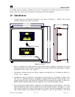
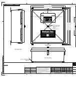
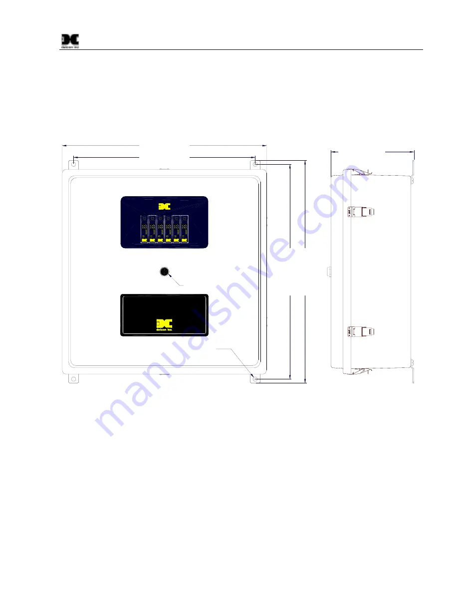
1. Securely mount the 610-N4X-SA Enclosure in accordance with figure 1.  Stainless Steel version 

mounting footprint is the same as that shown. 

22.75in [577.85mm]

26.8in [681.99m

m]

Detcon Inc.

www.detcon.com

RESET/ACK

BUTTON

Houston Texas

Gas Detection Control System

www.detcon.com

Houston Texas

Detcon Inc.

10.4in [263.91mm]

27.8in [707.39m

m]

25.59in [649.94mm]

Mounting Holes R0.28in [R7.14mm]

Reset/Ack Push Button

ALM 2

ALM 1

FAULT

MODEL 10

ALARM
RESET

TEST

ALM 2

ALM 1

FAULT

MODEL 10

ALARM
RESET

TEST

ALM 2

ALM 1

FAULT

MODEL 10

ALARM
RESET

TEST

ALM 2

ALM 1

FAULT

MODEL 10

ALARM
RESET

TEST

ALM 2

ALM 1

FAULT

MODEL 10

ALARM
RESET

TEST

ALM 2

ALM 1

FAULT

MODEL 10

ALARM
RESET

TEST

ALM 2

ALM 1

FAULT

ALARM
RESET

TEST

ALM 2

ALM 1

FAULT

ALARM
RESET

TEST

ALM 2

ALM 1

FAULT

ALARM
RESET

TEST

ALM 2

ALM 1

FAULT

ALARM
RESET

TEST

ALM 2

ALM 1

FAULT

ALARM
RESET

TEST

ALM 2

ALM 1

FAULT

ALARM
RESET

TEST

MODEL 10

MODEL 10

MODEL 10

MODEL 10

MODEL 10

MODEL 10

Model 610-N4X

www.detcon.com

d e t c o n  I n c .

Figure 1 

Mounting

2. Refer to installation and wiring detail of remote mount sensor assemblies as detailed in the Sensor

Instruction Manual.  Terminate field wiring from sensors on the 610-N4X-SA motherboard. Terminals
are labeled “Sensor” (mA, + and –, Figure 2).

3. If applicable, terminate the discrete 4-20 mA outputs to external device(s).  Terminals are labeled “4-

20 Out” (+ and –, Figure 2).

4. If applicable, terminate the RS-485 serial output to external device(s).  Terminals are labeled “RS-

485” (A+, B–, and Shield, Figure 2). If applicable, terminate RS-485 Shield to Earth Ground via the
jumper tab located to the left of the RS-485 terminals. Place the jumper on the bottom 2 contacts to tie 
RS-485 shield to Earth Ground or place the jumper tab on the top two terminals for storage. 

5. There are three fused 5Amp 120VAC outputs for every Alarm Relay and the Fault Relay. These Fuse

Block Terminals are located near the bottom center of the enclosure (Figure 3 and Figure 4).  To the 
left of the Fuse Blocks are as many Thru-blocks tied to Neutral. Based on the application and use of 
relay contact outputs, all annunciators should be connected to these output terminals. All wiring 

610-N4X-SA Instruction Manual

Rev. 0.1

Page 3 of 8 

Summary of Contents for 610-N4X-SA

Page 1: ...ouston Texas Gas Detection Control System www detcon com Houston Texas Detcon Inc Operator s Installation and Instruction Manual Covers 3 and 5 relay Stainless and Fiberglass Enclosures DETCON Inc 320...

Page 2: ...Model 610 N4X SA This page left intentionally blank 610 N4X SA Instruction Manual ii...

Page 3: ...2 1 Start Up 6 3 0 Maintenance Repair 6 4 0 Spare Parts List 8 5 0 Warranty 8 Table of Figures Figure 1 Mounting 3 Figure 2 Motherboard Schematic Wiring Diagram 4 Figure 3 Component Layout 5 Figure 4...

Page 4: ...ank Shipping Address 3200 A 1 Research Forest Dr The Woodlands Texas 77381 Mailing Address P O Box 8067 The Woodlands Texas 77387 8067 Phone 888 367 4286 281 367 4100 Fax 281 292 2860 www detcon com s...

Page 5: ...r Discrete output terminal strips located on the controller motherboard are provided for sensor terminations The 4 20 mA outputs for remote recording devices and an RS 485 serial ModBus output are loc...

Page 6: ...le applying power to annunciators attached to alarm 1 H2S or LEL Low Alarm 1 conditions can be Acknowledged and Reset via the RESET ACK Switch on the front panel of the unit Alarm 2 H2S LEL High Durin...

Page 7: ...MODEL 10 MODEL 10 MODEL 10 MODEL 10 MODEL 10 MODEL 10 Model 610 N4X www detcon com d e t c o n I n c Figure 1 Mounting 2 Refer to installation and wiring detail of remote mount sensor assemblies as d...

Page 8: ...6 5 4 3 2 1 14 13 12 11 10 9 8 7 6 5 4 3 2 1 CH1 P12 P16 CH1 4 20mA FAULT VDC Alarm 2 Alarm 1 Fault Out COM NC ALM1 ALM2 GND Shld B A VDC VAC GND VDC N L1 RED BLK N L1 Sensor NO COM NO NC COM NO NC m...

Page 9: ...D ALM COIL COMMON ALARMS ALM 1 FAULT VDC ALM 2 RS 485 ALM POWER L1 N N GND A B Shld OUT 4 20 FAULT NO C NC NO C VDC IN ALM RESET L1 SENSOR ALM2 NC NO C NC mA CH1 CH2 CH3 CH5 CH4 CH6 VAC IN P4 P5 P7 P7...

Page 10: ...sure Figure 3 and L1 N EARTH in Figure 6 If applicable connect 220VAC The power supply will accept both voltages 9 Connect Earth Ground to Terminal TB1 1 and Neutral to terminal TB1 5 Figure 6 7 8 9 5...

Page 11: ...gure 7 Backplane Configuration Jumpers Model 10 Control Modules A Model 10 control module may be changed by simply loosening its mounting screw and sliding the module out of its card cage See the Mode...

Page 12: ...ircuit Breaker 500 505000 000 Low Voltage Cut off PCB If applicable 3423 2 12V 2 9Ah Battery If applicable 5 0 Warranty Detcon Inc as manufacturer warrants under intended normal use each new Model 610...

Page 13: ......

Page 14: ......

Page 15: ......

Page 16: ......

Page 17: ......

Page 18: ......

Page 19: ......

Page 20: ......

Reviews: