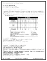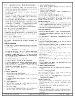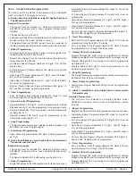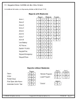
DS7080iP-32 Reference Guide Copyright © 2001 Detection Systems, Inc. P/N 39818D Page 55
#87 Display “AC Power Failure”
1. Not enough AC voltage or current load
too great for transformer.
2. AC not present.
3. No AC out of transformer.
1. Make sure proper transformer is used
(see AC Input note in Section 3.0).
2. Make sure panel is not connected to a
switched outlet that has been turned off.
3. Blown transformer fuse. Replace
transformer.
4. Load too great for transformer. Place
meter on AC scale and select the correct
setting for A or mA. Place meter wires in
correct position for A or mA scale.
Disconnect one side of the AC and place
your meter in series with the transformer
and panel. Current draw should not
exceed 2 Amps under load.
14.0
Troubleshooting Guide
#87 Display “ Battery Trouble”
1. Battery low or missing.
1. Replace or reconnect battery.
After replacing battery perform a System
Reset to see if it will restore. Battery may
take some time to charge.
Battery should be load tested prior to
installation.
Keypad displays “Control Trouble # 87”
but command does not work.
1. More than one keypad shares the same
address.
2. Set for commercial mode.
3. Keypad yellow wire missing or shorted.
1. Correctly set address jumper(s) for that
keypad.
2. PIN required before #87.
3. Check keypad wiring
#87 display “Keypad Fault”
1. Keypad Yellow, Green or Red wire
missing from another keypad
This will not display if this is the
faulted keypad. It is intended to show
status on other keypads.
1. Check keypad wiring.
Keypad displays “DSI Version 2.00
Copyright 1994” or alpha locked up.
1. LCD keypad has been programmed as
an LED keypad.
1. Get into programmers mode by using
programmers code. No visual indication
will be given.
Press [0] [0] [7] followed by the correct
data digits as shown in Address 007; end
with [#]. Keypad alpha should restore.
Keypad displays “Not programmed see
install guide”
1. Address jumper not set on keypad.
2. Not programmed.
1. Set address jumper on keypad.
2. Check Program Address 007
.
#87 displays “Zone Trouble” followed by
zone number.
Refer to “System Faults” for Trouble Zone
trouble shooting.
1. Zone is in trouble.
Normal loop voltages should read as follows:
short = 0.00 - 1 Vdc
normal = 2.5 - 4.5 Vdc
open = 6 - 7 Vdc
1. Check loop wiring.
Check loop Programming Address 034-037.
Remember N/O devices are alarm
on short, trouble on open. N/C
devices are alarm on open, trouble
on short.
Trouble zone not activating.
Not enabled or wired incorrectly.
Check Program Address 003
.
Check wiring.


