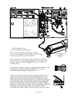
R5
Diff.
Adj.
Door operator signal is triggered
after latch retraction and time is
adjustable from 0.5 to 3 seconds
Operator signal delay time
is adjusted by R5.
Turn CW to increase delay time
if R21 does not supply enough
delay
Indicator turns green when operator
signal door is active
Door Operator Signal and Indicator
Door Signal
Terminal 14 is common
Terminal 13 is normally closed
Terminal 15 is normally open
Terminals are connected
to a SPDT dry contact relay
13
15
14
N.C.
N.O.
com
Control Inputs
7 8
3 4
5 6
Input 1
N.O.
Switch
N.O.
Switch
Input 2
N.O.
Switch
Input 3
Door Hold Select
Increase
Door Outputs
Two Door
Systems Only
Door 1 Out
Door 2 Out
D
oo
r 2
P
ow
er
9
+
J3
Indicator turns red
when door is active
10
-
+
12
11
J2
D
oo
r 1
P
ow
er
-
com
14
15
N.O.
Door Signal
Indicator turns green when operator
signal door is active
Door Operator Signal and Indicator
13
N.C.
Door Operator Signal Delay
Door Signal
Delay Adjust
R21
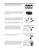
9: Control Inputs. These require a normally open contact.
The door latch will activate and hold once the circuit between
the terminals of Inputs 1 (J6) , 2 (J5) or 3 (J4) is closed.
10: Door Hold Delay Adjust. This potentiometer adjusts the length of
time the latch is held retracted once the input switch is released.
Turn clockwise to increase the latch hold time up to a maximum
of about 30 seconds.
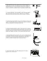
11: Output to ER Device. This terminal block (J2) is connected
to the ER power wires. Observe correct polarity. Red from the ER
is positive (terminal 11) and black is negative (terminal 12). The
board is also and - at the connections as well.
12: Door Output Activity Indicator. The LED glows red
when the output voltage to the latch retraction device is energized.
13: Door Opener Output. Connector J7 is connected to
a relay. It can be used to signal a door opener or other
device that the latch is retracted. It is delayed and goes
active after the latch retraction occurs. The amount of the
delay is .5 to 3 seconds and is adjusted by Item 15 below.
14: Door Operator Status Indicator. The status LED will
glow green when the relay is energized.
15: Door Operator Delay Adjust. There are two potentiometers
that adjust the delay of the operator signal relay. Under normal
use, only R21 should be used. Turn clockwise to increase the
delay between the door latch retraction and the relay being
energized. Turn R5 only if a longer delay time is needed.
101339 Page 4


