104887 Page 9
40-3/8"
38"
Align rod holes with bottom latch
(round
DIM A
to nearest value shown)
DIM A
(device C at
distance from floor )
L
39"
40"
Bottom Rod
p/n: 105098
use HOLE
40-3/4"
X
Y
Z
V
W
BOTTOM ROD
p/n 105098
CLIP
p/n 103551
PIN
p/n 105248
BRACKET
BOLT
p/n 103536
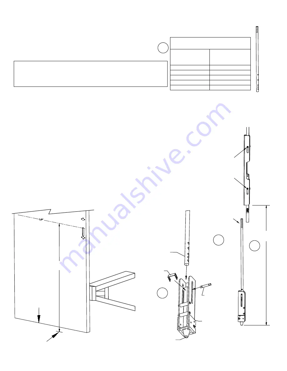
STEP 4:
BOTTOM ROD / LATCH ASSEMBLY & ADJUSTMENT
(Disregard if TRO device is being installed)
NOTE: SLOTS
MUST
BE IN
POSITION SHOWN
(SCREWS AT THE TOP)
DURING ADJUSTMENT
Adjust length here
1/2" MINIMUM
thread engagement
required
DIM C
V
W
X
Y
Z
HORIZONTAL DEVICE
INNER FACE OF
DOOR SHOWN
BOTTOM OF DOOR
FINISHED FLOOR
DIM A
4a. Using
DIM A
as measured in step 1,
use chart to determine pinning location.
If
DIM A
is
less
than 37-1/4" from finished floor, a new pin hole
must be drilled through 105098 rod. Subtract the centerline dimension
from 38" and measure up this distance from hole V. Mark and drill .189
diameter hole (#12 drill).
Note: If hole V or W is used (or if new hole is drilled closer to threaded end),
trim off UNTHREADED end of rod as needed to allow rod to slide into bottom
bolt far enough to pin.
4b. Remove clip 103551 and slide pin out. Place bottom rod 105098 into
bolt, line up holes and replace pin and place clips into pin grooves.
4c.
DIM C
is the target length.
For no threshold or threshold 1/2" or less:
DIM C
= measured
DIM A
minus 8".
For threshold greater than 1/2":
DIM C
= measured
DIM A
minus 8" minus threshold height
The bottom bolt vertical travel from fully extended to fully retracted
is approximately 9/16.
4d. Thread bottom rod into centerlift mechansim to achieve
DIM C
(within 1/16").
4a
4c
4d
4b
ROD
P/N 105098


