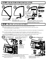
STEP 10:
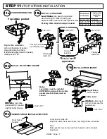
HANG DOOR / ASSEMBLE DEVICE TO DOOR
COMPLETE BACKPLATE MOUNTING
INSTALL DEVICE TO BACKPLATE
1
L
2
Check for device and door frame clearance.
If no cut-off needed, proceed to the next page.
CUT
fillerplate and extrusion STRAIGHT & SQUARE
to desired length and deburr.
SECURE with tape before cutting.
Minimum
Fillerplate
Length
SLIDE
endcap assembly
onto extrusion
CAUTION:
CHECKING FOR DEVICE CLEARANCE
(Cut-Off procedure if required)
Type
Length (L)
2-1/2"
LD
3"
HD/CD
For aluminum Advantex finish cutdown applications:
After cutting, the baseplate extrusion can be reversed
to place the cut end inside the head cover.
To do so, loosen the setscrew inside the aluminum
baseplate extrusion and slide extrusion out, reverse,
& slide back in. Tighten setscrew.
INSTALL DOOR ONTO FRAME PER MANUFACTURER'S SPECIFICATIONS
INSTALL
with (2) screws
104924 Page 15
10f
10d
10a
10e
INSTALL
backplate
with (4) lockwashers
& screws
OR
screws & sexnuts
OR *
If using sexnuts, install here.
10-24 x 1/4"
Install device to backplate & fasten with 2 screws.
Depress pushpad appropriate amount
to line up lift pin with tabs
Drill #7 or 13/64" for threaded hole
Right Hand Reverse
(RHR)
If link is not in uppermost position on the centerlift,
carefully remove "E" clips and reposition link on
top pin of the centerlift and replace "E" clips.
Verify carriage moves up and down smoothly when
pushpad is depressed and released.
Rehanding procedure
if required
HANDING INDICATOR
ON CENTERLIFT
Left Hand Reverse
(LHR)
MOVE LIFT PIN & SETSCREW TO
BOTTOM POSITION ON CARRIAGE.
LIFT PIN
MUST
BE ON
BOTTOM
Remove setscrew then liftpin which
screws out of the back.
NOTE: LINK MUST ALWAYS
BE IN TOP POSITION
setscrew
liftpin
10b
Drill exterior door face 1/2" (With Trim)
or 3/8" (Without Trim).
Drill interior door face 9/32".
and
or
REFER TO TRIM INSTRUCTIONS AT THIS TIME, IF APPLICABLE
10a
Lift pin protruding from back of centercase
MUST
be inserted
BETWEEN
these two tabs.
Door OPEN position,
latches RETRACTED


