Table A: Selector Switch Functions
STATUS
INDICATOR
STATUS DESCRIPTION
OFF*
No indication that device is armed or disarmed.
ON
DISABLE AUTO
REARM
STATUS DESCRIPTION
OFF
DEFAULT: Alarm will automatically rearm 2 minutes after alarm
has been activated and door closed.
Custom settings can be programmed by DETEX.
ON*
Alarm will not automatically rearm after alarm has been
activated.
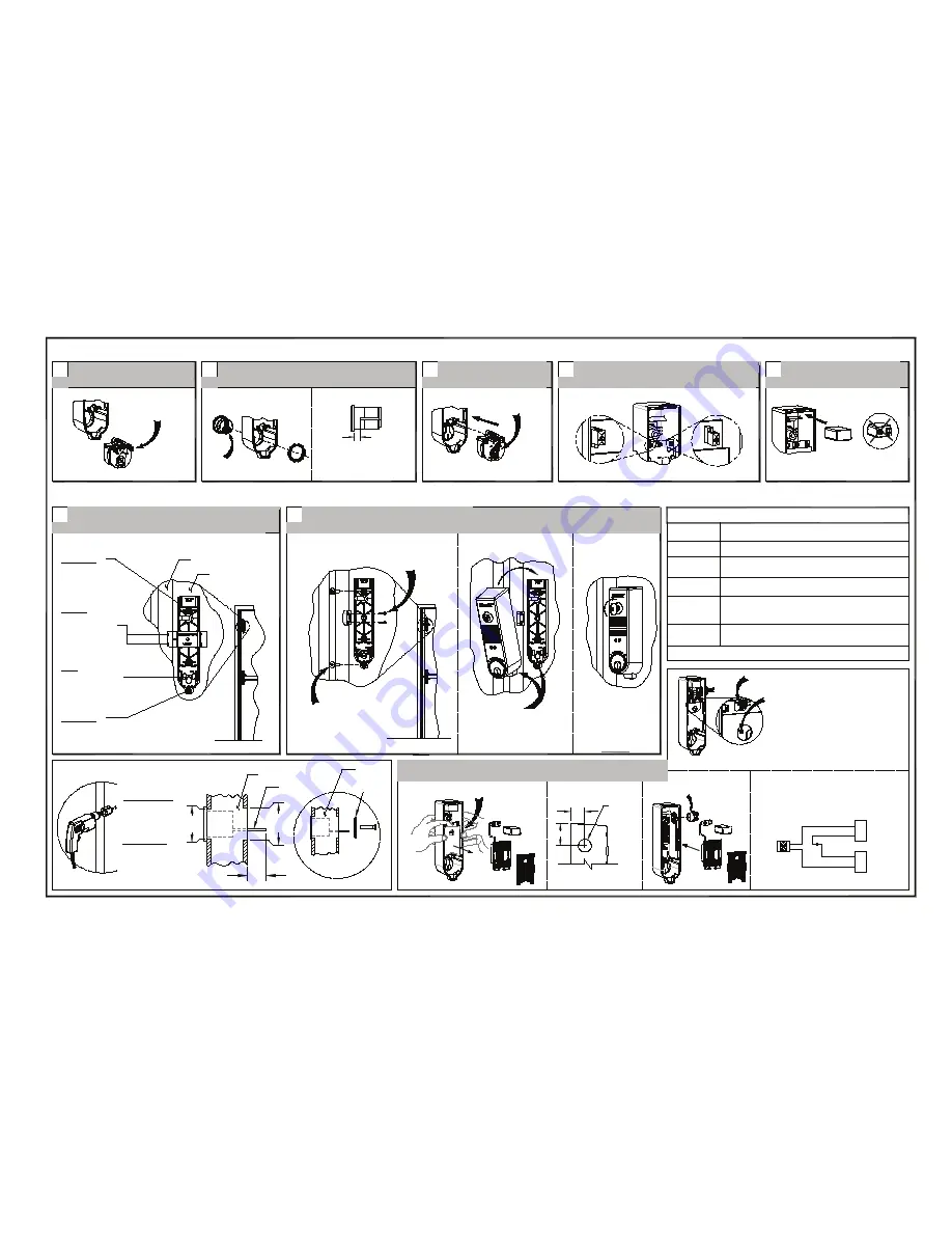
STEP 6: PREP DOOR
STEP 7: INSTALL DEVICE
STEPS 1-5: PREP DEVICE
Mark/drill backplate and magnet holes on door
and frame/mullion
*Default settings; **Will shorten battery life
DOOR
ASSEMBLE
6
Install magnet, backplate and cover
Install magnet with (2)
#4-40 or #4 screws
Install backplate with (2)
#1/4-20 or #14 screws
7
FRAME/MULLION
LHR installation shown
for reference only
DOOR
NOTE: Remove locator and backplate prior to drilling mounting holes
Set cam position
as shown
Re-install cam assembly
3
CORRECT
WRONG
Connect 9-volt battery and
install as shown
5
Remove cam assembly from
cover
Unfasten (2) screws
1
Install mortise cylinder with cylinder nut provided
Cam orientation
as shown
2
4
DISABLE AUTO
REARM
STATUS
Turn key CW
to lock cover
OKC
ARMED - red LED blinks approximately every 3 seconds.**
DISARMED - green LED blinks approximately every 3 seconds.**
Hook at bottom, then tilt
cover over backplate
Mortise cylinder
NOT provided
Backplate
Drill #7 for #1/4-20
machine screws
Drill 7/32" or 3/16" for
#14 sheetmetal screws
Magnet
Drill #43 for #4-40
machine screws
Drill #44 for
#4 sheetmetal
screws
Backplate
Drill #7 for #1/4-20
machine screws
Drill 7/32" or 3/16" for #14 sheetmetal screws
INDICATOR
1-1/2
Fitting or nut NOT included
Cut (JP1) jumper
Flex walls outward to remove guard & board
1"
Drill 7/8 dia
(1) place
Screw wires to (P1) terminal block
MULTI-DOOR FUNCTION
Recommended hole size
(Recommended installation)
White
Black
Terminal
P/N: PP-5107
White
Black
Mag
Switch 1
Switch 2
Mag
(18ga Max wire dia)
3/4"
1-3/8"
Dia
DOOR
TAILPIECE
PROVIDED
NOTE: For "Key Stop", See Figure 2
Where applicable,
mark TOP hole center & drill
1/4" dia. pilot hole through door
See OKC INSTALLATION
Drill 1-1/4" hole
through outside
door face
Drill 1-3/8" hole
through inside
door face
Cylinder Side:
Device Side:
1-1/4"
Dia
IMPORTANT!
Ins No: 101321
Collar required if distance
is greater than 5/16".
7-pin cylinders ONLY
Install mortise cylinder with cylinder nut provided
Optional collar can be ordered
from Detex (p/n: ECL-1595)
Diagram shown typical for two door magnetic
switches:
MS-1039S & MS-1059S wire in series.
MS-2049 SHOWN (Red wire not used)
Outside Key Control Installation
Rim cylinder - Detex P/N: ECL-445K-X
Set selector switch functions (See Table A)
Default settings
Closed contact when door is closed
NOTES:
1. If wire runs longer than 10 feet,
must use twisted pair
2. 1/16" slotted jeweler screw driver required.
3. If internal contact is used DO NOT
cut jumper (JP1)


