14
GB
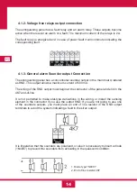
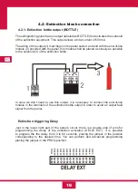
4.1.3- General alarm Sounder output Connection
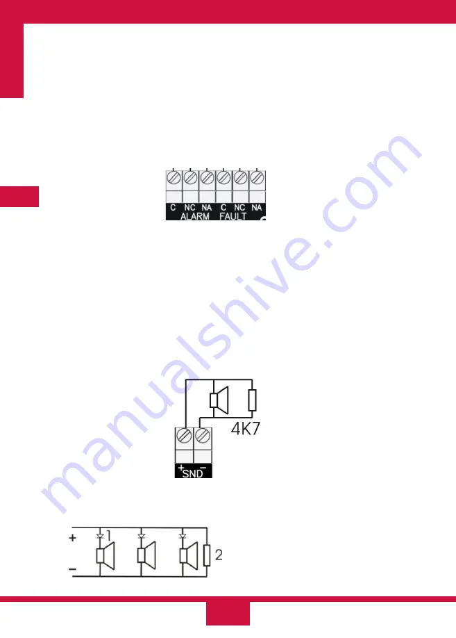
The extinguishing panel has a conventional sounder output in the main board, labeled
as SND. This output allows a maximum current of 500 mA.
The wiring of the SND output must begin at the connector of the panel and end in the
4K7 end-of-line.
It is not permitted to make star-type derivations in the wiring, or install the sensing
element in the connector if you use the output SND. If you are not going to use one
of the sounders outputs, you must place an end of line resistor in the SND output
terminals to avoid the system indicating a fault in the siren output.
4.1.2- Voltage free relays output connection
The extinguishing panel has a fault relay and an alarm relay. These outputs become
active when there exist an alarm or a fault. The maximum current of the relays is 2 A.
The fault relay is energized and in case of power fault it will commute indicating the
corresponding fault.
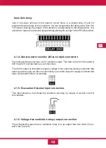
It is imperative that the sounders are polarized, or else it is necessary to insert a diode
(1N4007) to prevent the sounders from activating in the quiescent condition.
1. Diode type 1N4007
2. End of line resistor 4K7
Summary of Contents for CCD-103
Page 1: ...GB ES ES GUIDE MANUAL FR 3 Zones Conventional fire extinguishant control panel IT ...
Page 2: ......
Page 3: ...ES ES Central Convencional de 3 Zonas de detección y 1 Extinción MANUAL DEL USUARIO ...
Page 4: ......
Page 6: ......
Page 14: ...12 ES 4 Guía de conexionado de la PCB ...
Page 44: ......
Page 45: ...GB GUIDE MANUAL 3 Zones Conventional fire extinguishant control panel ...
Page 46: ......
Page 48: ......
Page 56: ...12 GB 4 PCB connection guide ...
Page 86: ......
Page 87: ...FR FR Centrale conventionnelle à 3 zones de détection et 1 zone d extinction MODE D EMPLOI ...
Page 88: ......
Page 90: ......
Page 98: ...FR 12 4 Guide de branchement de la PCB carte de circuit imprimé ...
Page 128: ......
Page 129: ...IT Central Convencional de 3 Zonas de detección y 1 Extinción MANUAL UTENTE ...
Page 130: ......
Page 132: ......
Page 140: ...12 IT 4 Guía de conexionado de la PCB ...
Page 170: ...55310300 2014 10 14 ...

