GB
19
5- Start-up Guide System
This chapter defines step by step how to start up with the extinguishing panel correctly.
5.1- System check
Before handling any other part of the system, please
verify the solenoid is disconnected from the bottle.
Before connecting the mains supply check the points listed below carefully:
•
Check that the equipment has been installed correctly.
•
With the help of a voltmeter to verify that there are no short or open circuits in the
zone lines, sounders, bottle output, sign, state 1, state 2, manual buttons and bottle
and door surveillances, verify also they have 4K7 end of line resistors.
•
Verify that the sounder circuits, sign circuit, state 1 and state 2 are connected with
the correct polarity.
•
Verify that the bottle output line is connected respecting the polarity and ensure it has
the end-of-line module.
•
Set the desired delay for the sounders.
•
Set the desired delay for the bottles triggering.
•
Set the desired operation mode.
Check that the mains voltage is 230V using a voltmeter and check that batteries have
a voltage of more than 24V.
5.2- System Supply
After reviewing all the points described above, the correct order to connect the power
is:
•
Connect the mains power supply.
•
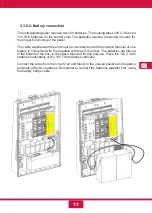
Connect the batteries.
If necessary, you can turn the panel on with only the battery connected, but it is
essential to press BAT to start the panel.
Once both power supplies are connected all the panel indicators should be turned off
except the green power LED. If you have programmed a sounder delay, you should
also see the sounder delay LED on.
If you notice any indication other than those described above, the origin of the problem
in the installation should be detected and the fault repaired before proceeding (see
problems).
Summary of Contents for CCD-103
Page 1: ...GB ES ES GUIDE MANUAL FR 3 Zones Conventional fire extinguishant control panel IT ...
Page 2: ......
Page 3: ...ES ES Central Convencional de 3 Zonas de detección y 1 Extinción MANUAL DEL USUARIO ...
Page 4: ......
Page 6: ......
Page 14: ...12 ES 4 Guía de conexionado de la PCB ...
Page 44: ......
Page 45: ...GB GUIDE MANUAL 3 Zones Conventional fire extinguishant control panel ...
Page 46: ......
Page 48: ......
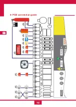
Page 56: ...12 GB 4 PCB connection guide ...
Page 86: ......
Page 87: ...FR FR Centrale conventionnelle à 3 zones de détection et 1 zone d extinction MODE D EMPLOI ...
Page 88: ......
Page 90: ......
Page 98: ...FR 12 4 Guide de branchement de la PCB carte de circuit imprimé ...
Page 128: ......
Page 129: ...IT Central Convencional de 3 Zonas de detección y 1 Extinción MANUAL UTENTE ...
Page 130: ......
Page 132: ......
Page 140: ...12 IT 4 Guía de conexionado de la PCB ...
Page 170: ...55310300 2014 10 14 ...

