GB
27
•
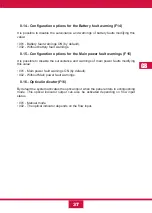
Automatic-manual mode.
•
Manual mode.
•
Disabled mode.
6.3.9- Manual Release Gas Extinguishing System (I)
Pushing this two keys ha the same effect than pushing the triggering extern button, it
will start the process of the “activated” state of the extinguishing panel.
6.4- Operating Modes of the detection block
6.4.1- Standby mode
The unit is in standby when there are no faults, alarms, disconnections or tests. In this
case, only the service warning light will be active and all the other warning lights and
sounds will be off.
The delay mode warning light may be active depending on the programmed delays.
6.4.2- Alarm mode
The unit is in alarm mode when any of the areas are in alarm mode. The alarm
indicators are as follows:
•
General alarm Led active:
Blinking if the alarm was caused by a detector or
continuous if it was caused by a manual call point.
•
Zone alarm Led active:
Blinking if the alarm was caused by a detector or continuous
if it was caused by a manual call point.
•
Acoustic warning active:
Continuous.
•
Alarm relay activation.
•
Sounders activation:
After the programmed delay has passed.
Actions in case of alarm:
Once it is in alarm state, you can do the following:
•
Press the silence key:
Silences the buzzer and activates the buzzer silenced LED.
•
Press the reset key:
The unit will return to standby. You should not reset the unit until
you have solved the cause of the alarm.
•
Press the sounders on key:
Cancels the programmed delay and activates the
sounders immediately. If the sounders are tripped, it will have no effect.
•
Press the silence sounders key:
If the sounders are active, they will be deactivated.
Summary of Contents for CCD-103
Page 1: ...GB ES ES GUIDE MANUAL FR 3 Zones Conventional fire extinguishant control panel IT ...
Page 2: ......
Page 3: ...ES ES Central Convencional de 3 Zonas de detección y 1 Extinción MANUAL DEL USUARIO ...
Page 4: ......
Page 6: ......
Page 14: ...12 ES 4 Guía de conexionado de la PCB ...
Page 44: ......
Page 45: ...GB GUIDE MANUAL 3 Zones Conventional fire extinguishant control panel ...
Page 46: ......
Page 48: ......
Page 56: ...12 GB 4 PCB connection guide ...
Page 86: ......
Page 87: ...FR FR Centrale conventionnelle à 3 zones de détection et 1 zone d extinction MODE D EMPLOI ...
Page 88: ......
Page 90: ......
Page 98: ...FR 12 4 Guide de branchement de la PCB carte de circuit imprimé ...
Page 128: ......
Page 129: ...IT Central Convencional de 3 Zonas de detección y 1 Extinción MANUAL UTENTE ...
Page 130: ......
Page 132: ......
Page 140: ...12 IT 4 Guía de conexionado de la PCB ...
Page 170: ...55310300 2014 10 14 ...

