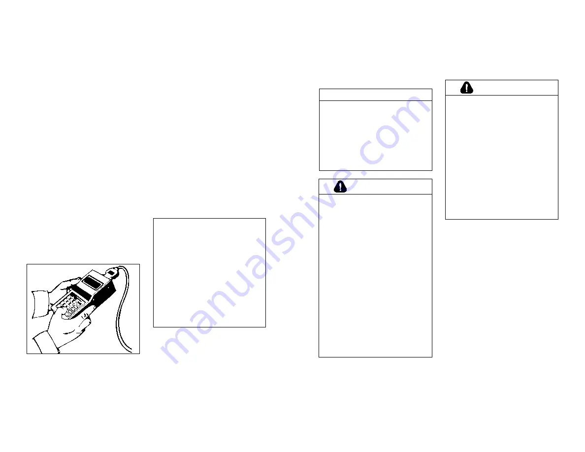
The diagnostic code can also be
obtained by the operator:
DDEC II Engines—
A “Diagnostic
Request” switch is provided which,
when pressed, will cause the “Check
Engine” light (CEL) to flash a code
number. It will, for example, flash
twice...pause...flash five times...pause.
In other words a code 25.
Code 25 indicates all systems are
working satisfactorily.
DDEC III Engines—
The
active codes
will be flashed on the “Stop Engine”
light (SEL) in the order of most recent
to least recent occurrence based on
engine hours. If there are no active
codes, a code “25” will be flashed.
The
inactive codes
will be flashed
on the “Check Engine” light (CEL) in
the order of most recent to least recent
occurrence based on engine hours. If
there are no inactive codes, a code
“25” will be flashed.
Diagnostic Data Reader J38500
Note that only one lamp will be
flashing codes at any time. When
code flashing is initiated, the active
codes (or code “25”) will be flashed on
the SEL. Then the inactive codes (or
code “25”) will be flashed on the CEL.
When all the inactive codes (or code
“25”) have been flashed, the process
of flashing all the active codes fol-
lowed by all the inactive codes will
repeat until the conditions for code
flashing are no longer satisfied.
The codes will continue to flash and
repeat as long as the “Diagnostic
Request” switch is held in the “On”
position with the ignition on. Other
diagnostic codes are shown in the
charts (pages 18-19).
NOTICE:
If a DDEC II vehicle engine
is equipped with an OEM-supplied
diagnostic switch, the switch must
NOT be switched on when operating
the vehicle. If this is done, the diag-
nostic mode line will be grounded,
and the throttle will be forced to idle,
affecting vehicle operation. The
throttle will also go to idle if pins “A”
and “M” in the Diagnostic Data
Reader (DDR) connector are
jumpered together. This condition
will not occur when the Diagnostic
Data Reader is used.
Welding Precaution
16
17
NOTICE:
To prevent damage to the DDEC
electronic control system, discon-
nect battery power and ground
cables and the 6-pin power connec-
tor at the ECM (electronic control
module) before welding.
Failure to
isolate the DDEC system from
high current flow can result in
severe ECM damage.
CAUTION:
The operator of a DDEC-equipped
engine should know the extent of
the warning system on his vehicle,
in order to bring it to a safe stop in
the event of an engine malfunc-
tion. A description of the warning
system and detailed instructions
regarding its operation should be
obtained from the owner, the seller
or the manufacturer of the vehicle.
This information may also be
obtained at any authorized Detroit
Diesel service outlet.
To be confronted with a power-
down/shutdown situation without
knowing how the system works
could cause the vehicle to stop in
an unsafe location, posing the
possibility of damage to the vehi-
cle and a threat to the safety of the
operator.
CAUTION:
The operator of a DDEC-equipped
vehicle must not attempt to use or
read a diagnostic data reader of
any kind while the vehicle is oper-
ating. Doing so can result in loss
of control, which may cause vehi-
cle damage and may result in per-
sonal injury.
When engine or electronics sys-
tem diagnosis is required on a
DDEC-equipped vehicle, this must
be done by a person other than
the operator. The operator must
maintain control of the moving
vehicle while the assistant per-
forms the diagnosis.
Summary of Contents for 92 Series
Page 41: ...NOTES 77 NOTES 76 ...
Page 42: ...NOTES 78 ...


