background image

SECTION 4

DDFP

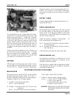
GOVERNOR SOLENOID-ADJUSTMENT

The mechanical governor is controlled by a DC solenoid. A

spring loaded yield link is included as part of the e xternal

linkage from the run/stop lever to governor solenoid.

IMPORTANT:

To insure the engine will produce rated

nameplate horsepo wer, the g ap be-

tween the yield link and the solenoid

plunger must be properly adjusted.

(Refer to Figure 3.)

YIELD LINK GAP CHECK

Position the mode selector switch on the instrument panel

(Fig. 3, Page 32), to the MANUAL position. Manually push

the solenoid plunger into the solenoid.  When the plunger is

at full tra vel, the hold coil magnetic f ield will hold the

plunger, linkage and the run/stop le ver in the run position.

Push on the plunger spring bolt, not the linkage or the lever.

Check the gap at the narrowest point and adjust if necessary,

(Refer to Fig. 3).  After the check is completed return the

mode selector switch to the AUTOMATIC position.

WARNING:

DO NOT lea ve the MODE SELECT OR

switch in the MANU AL R UN position

during  AUTOMATIC operation. (The

controller will be una ble to stop the

engine and O VERHEAT D AMAGE

WILL RESULT)

Page 46-A

53 SERIES ENGINES

Adjust the Gap by loosening the Lever Clamping Bolt (Fig.

3), and rotating the Run/Stop Lever on the governor shaft to

the desired position and re-torque the clamping bolt. Re-

check the gap and repeat adjustments if necessary. After the

check is completed return the mode selector switch to the

AUTOMATIC position.

After the gap has been properly adjusted, and with the gov-

ernor solenoid de-ener gized, in the ST OP position, adjust

the Plunger Stop Bolt. Set at zero clearance with the Plunger

Spring Bolt, then turn one full turn clockwise and lock with

the Jam Nut.

WARNING:

DO NOT lea ve the MODE SELECT OR

switch in the MANU AL R UN position

during  AUTOMATIC operation. (The

controller will be unable to stop the

engine and O VERHEAT D AMAGE

WILL RESULT)

When the adjustments have been completed, start the engine

from the ENGINE CONTROLLER (AEC), using the MAN-

UAL mode. Verify the Gap Dimension again, then stop the

engine. Return all controls to the AUTOMATIC mode.

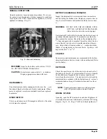
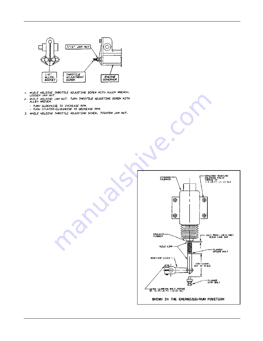
Figure 3 - Shown in the Energized/Run Position

Figure 2 - Speed Adjustment 71 & 92 Series

Summary of Contents for DDFP Series

Page 1: ...enance Instructions Manual DDFP SERIES ENGINES FOR FIRE PUMP APPLICATIONS This manual covers Detroit Diesel engines modified by Clarke DD A for fire pump service Printed in U S A LISTED APPROVED LISTED MP 4 7 96 C13194 FM ...

Page 2: ...ation ID Identification IP Instrument Panel I 53 In Line Cylinder arrangement 53 Series DDC Engine I 71 In Line Cylinder arrangement 71 Series DDC Engine NA Naturally Aspirated NC Normally Closed NO Normally Open NFPA National Fire Protection Association P N Part Number PSI Pounds Per Square Inch PTO Power Take Off RPM Revelutions Per Minute SAE Society of Automotive Engineers S N Serial Number T ...

Page 3: ... Section 3 2 16 Air System Operation 16 Maintenance Service Procedures 19 Exhaust Operation 19 Lubrication System Section 3 3 20 Operation 20 Lubricating System Schematics 21 Maintenance Service Procedures 22 Cooling System Section 3 4 25 Operation 25 Maintenance Service Procedures 30 Electrical System Section 3 5 31 Operation 31 Maintenance Service Procedures 35 DC Wiring Diagram 37 38 Engine Hea...

Page 4: ...oward the exhaust valves pro duces a scavenging effect leaving the cylinders full of clean air when the piston again covers the inlet ports As the piston continues on the upw ard stroke the exhaust valves close and the charge of fresh air is subjected to com pression Fig 1 2 Compression Shortly before the piston reaches its highest position the required amount of fuel is sprayed into the comb usti...

Page 5: ...n the eng ine A gear type pump dr aws oil fr om the oil pan through an intak e screen through the oil f ilter and then to the oil cooler From the oil cooler the oil enter s a longitu dinal oil g allery in the c ylinder b lock where the suppl y divides and is channeled to the turbocharger if included to the cam and balance shaft end bear ings and c ylinder head with the remainder going to the main ...

Page 6: ...led 6 Turbo Aftercooled D D F P L 6 V T Figure 3 Clarke FM UL ULC Model On some engines you may find different engine rated horse power and oper ating RPM on the r ocker cover name pla te than on the FM UL ULC ta g attached to the f lywheel hous ing The FM UL ULC tag is the official power data and takes presi dence over the rocker cover data See Page 1 N Naturally Aspirated T Turbocharged A Turboc...

Page 7: ... to Full Load Heat Exchanger with pressure cap High water temperature switch Instrument panel with water temperature oil pressure and voltmeter Junction box DC control for connection to engine controller Low oil pressure switch Manual over ride of automatic operations including instruction plate Manual start contactors two provided on each engine Oil filter s full flow with by pass Oil pan heater ...

Page 8: ...flywheel housing Figure 5 Figure 6 The DDC model and S N are found on the manuf acturer s I D label Fig 6 on the v alve rocker cover This model is also stamped on the engine block On the Inline engines the model number is stamped into the cylinder block casting on a machined pad abo ve and to the right of the engine blower On the VEE engines the number is stamped at the right front of the block ju...

Page 9: ...Each Engine Model Refer To Technical Data Section 5 Type Number of Cylinders Bore inches Bore mm Stroke inches Stroke mm Compression Ration T Eng Compression Ration N Eng Total Displacement cub in Total Displacement liters Number of Main Bearings 2 Cycle 3 3 875 98 4 5 114 18 7 1 21 0 1 159 2 61 4 08FA 2 Cycle 8 4 84 123 5 127 17 1 736 12 07 5 L8FA 08FH 2 Cycle 8 4 84 123 5 127 15 1 736 12 07 5 12...

Page 10: ...SECTION 1 DDFP Page 7 Fig 8 VEE Engine Cylinder Designation and Firing Order Fig 7 Cylinder Designation and Firing Order 3 IN LINE 4 IN LINE ...

Page 11: ...t the authorized DDC Distributor Dealer if you require assistance with this item 9 Unbox and inspect air cleaner element for damage or de terioration Install air cleaner element on engine 10 Install batteries battery cables and service batteries as required by manufacturer See battery recommendation under Section 3 11 Install exhaust system A vertical exhaust outlet is fur nished for customer cont...

Page 12: ... oil specif ied under Section 3 Lubricating Oil Running Inspection While the engine is running at operating temperature check for coolant fuel or lubricating oil leaks Tighten the line Drive Belts Adjust the alternator drive belts as recommended under the Preventive Maintenance Section 2 Storage Battery Check the batteries The top should be clean and dry the ter minals tight and protected and the ...

Page 13: ...DDFP SECTION 2 Front View V 71 Page 9 A Front View I 71 Right Side View I 71 Right Side View 6V 71 ...

Page 14: ...Page 9 B SECTION 2 DDFP Front View 12V 92 Left Side View 12V 92 Front View V 92 Right Side View V 92 ...

Page 15: ... switch Crank terminate SW 1 adjustment should be done reading engine crankshaft speed at the front of the engine using a hand held tachometer For starter protection and optimum engine stability this switch should be calibrated to 1000 RPM Overspeed SW 2 adjustment should be done r eading en gine crankshaft speed at the front of the engine using a hand held tachometer This switch should be calibra...

Page 16: ...e X 18 Governor Run Stop Mechanism X 19 Jacket Water Heater X 20 Wiring System X 21 Coolant Hose Inspection X R See Parts Information Section 6 for Lubricating Oil And Coolant Analysis Kits IMPORTANT Set AEC to of f while servicing engine Before turning the AEC to the off position check with the maintenance and security supervisors to v erify that all de partments concerned will be alerted of the ...

Page 17: ...e operating speed RPM Much of the data v aries by operating RPM check the FM UL ULC certification tag on the engine flywheel housing for this speed Section 3 1 Fuel System Section 3 2 Air Intake Exhaust System Section 3 3 Lubrication System Section 3 4 Cooling System Section 3 5 Electrical System Section 3 6 Falk Drive Coupling Since the injector is one of the most important and careful ly constru...

Page 18: ... lines the I 53 filters are mounted the reverse of all others The Primary Filter mounts to the c ylinder head abo ve the pump The Secondary filter mounts to the coolant w ater inlet elbow below the fuel pump Inlet fuel check valves are always located on the discharge side of the sec ondary filter DIESEL FUEL RECOMMENDATIONS The quality and grade of fuel used is a very important factor in obtaining...

Page 19: ...o vides speed control of the engine The certified engine speed shown on FM UL ULC label has been preset at the f actory Minor speed adjustments can be made in the f ield to meet specific installation condition generally 50 RPM maximum The go vernor is controlled by the R UN STOP solenoid This solenoid is activated by a signal from the AEC A man ual over ride switch on the instrument panel placed i...

Page 20: ...rom a treated to an untreated tank Diesel fuel soluble type such as Biobor manufactured by U S Borax or equivalent treats the fuel itself and therefore the entire fuel system Please follow manufacturer s recommendations on useage of these materials Engine Out of Fuel The problems of restarting an engine that has run out of fuel involves the entire fuel system After the fuel is e xhausted from the ...

Page 21: ...filter efficiency by re spraying with oil NOTE Do not attempt this while engine is running NOTE Do not over oil AIR INTAKE OPERATION In the scavenging process employed in the engines a charge of air is forced into the c ylinders by the blo wer and thor oughly sweeps out all of the b urned gases through the exhaust v alves This air also helps to cool the inter nal engine parts particularly the e xh...

Page 22: ...SECTION 3 2 DDFP AIR FILTER SERVICE INSTRUCTIONS Figure 1 Air Filter Service Instructions Page 17 ...

Page 23: ... I 71 Liquid accumulation in the air box will result if a drain tube becomes plugged Remo ve the drain tubes and connectors from the c ylinder block and clean them thoroughly when necessary rocker arm compartment Here it is e xpelled through a vent pipe attached to the rock er cover breather assembly Turbo charged I 71 engines additionally use a breather attached to the front left side of the c yl...

Page 24: ...ection muffler exhaust piping and its conf igura tion In addition to providing engine exhaust data and back pressure limitations Clarke of fers a service to installers through the local Pump OEM Dealer for making recom mendations on e xhaust system sizing for specif ic installa tions If the exhaust system should become restricted the hot ex haust gases cannot escape from the engine This condition ...

Page 25: ...of the oil cooler sys tem Please refer to the technical data Section 5 for specif ic lube oil temperature and engine coolant temperature ranges for each engine model LUBE OIL FILL On I 71 engines the oil fill is located on the right rear On the VEE engines it is found in the right bank v alve rocker cover On the 53 Series engine the oil fill is also located on the rocker cover See technical data S...

Page 26: ...SECTION 3 3 DDFP Fig 1 I 53 Lubricating System Schematic Fig 3 V 71 92 Lubricating System Schematic Fig 2 I 71 Lubricating System Schematic Page 21 ...

Page 27: ... and API American Petroleum Institute Service Designation Both of these properties are displayed in the API Symbol which is illus trated within the specif ic requirements For DDFP engines the proper lubricant must also possess a sulfated ash content below 1 0 mass Lubricating oils for Non T actical Military usage currently SAE Viscosity Grade 40 API Classification CDII or CF2 Sulfated Ash less tha...

Page 28: ...in a DDFP engine Refer to Parts Information Section 6 to order Oil Analysis consists of a series of laboratory tests conduct ed on the engines lubricant Some tests sho w the condition of the engine and others show the condition of the lubricant Refer to Fig 4 for warning limits Various Methods Elemental Analyses are conducted using either emission or atomic absorption spectroscop y Neither method ...

Page 29: ...DDFP SECTION 3 3 Page 24 OIL VOLUME For specific oil quantities please refer toTechnical Data Sec tion 5 for each engine model listing Fig 5 Typical Oil Fill Location ...

Page 30: ...c ylinder walls and cylinder heads and must be carried away from the engine It is the function of the Heat Exchanger to transfer w aste engine heat to the raw cooling water Inside the heat e xchanger tank Fig 1 is a heat e xchanger core somewhat similar to a miniature radiator Engine coolant circulates around the heat exchanger core while cool raw water from a tap on the pressure side of the f ire...

Page 31: ...s corrosion or a combination of these Chlorides and or sulf ates tend to accelerate corro sion while hardness percentage of magnesium and calcium salts broadly classif ied as carbonates causes deposits of scale Water within the limits specified in Fig 2 is satisfac tory as an engine coolant when properly inhibited Use of distilled water is ideal ANTIFREEZE Use an eth ylene glycol coolant lo w sili...

Page 32: ...tle white plastic bottle Fig 4 During initial filling of the cooling system it will be nec essary to fill the Recovery Bottle to the Cold Full line with the pre mix solution Start and run the engine as indicated abo ve After reaching normal operating temperature check the coolant le vel in the recovery bottle to verify that the level is at the Hot Full line if not add coolant to the bottle Followi...

Page 33: ... safe temperature for emer gency start purposes If pump room temperatures drop belo w 50 F 10 C oil heaters are required On the initial installation of each f ire pump engine it is the responsibility of the installing contractor to wire the heater to the pump room AC circuit See Section 3 Electrical AC Wiring Diagram Page 39 for correct wiring to the heater disconnect switch CAUTION Do not acti va...

Page 34: ...SECTION 3 4 DDFP Fig 8 Typical Cooling Loop Page 29 Fig 6 Engine Heaters Fig 7 Raw Water Connections I 53 V 92 I 53 V 71 or V 92 V 71 I 71 ...

Page 35: ...rements at 60 F 16 C and 95 F 35 C at specif ied engine RPM ranges Do not exceed raw water pressure allowance within the heat exchanger NOTE Although engine operating temperature may appear normal engine cooling may be compro mised and possible engine damage will result if raw water flow is reduced ZINC ELECTRODE A sacrifical zinc anode is included with each heat e xchang er Over a period of time ...

Page 36: ...ific operational instructions NOTE Prior to turning the AEC to an y position other than automa tic please read the paragraph labeled IMPORTANT in Section 2 Page 11 The engine DC starting and control system terminates at the DC junction box The junction box location varies on differ ent engine models one is typically sho wn in Fig 5 From this point the engine is electrically connected to the auto m...

Page 37: ...DDFP SECTION 3 5 Page 32 Fig 2 Emergency Operating Instructions Fig 3 Automatic Manual Mode Selector Fig 7 Instrument Panel Fig 4 Manual Contactors Fig 5 DC Junction Box Fig 6 Governor Solenoid ...

Page 38: ...pring action INSTRUMENTATION Figure 7 Page 32 sho ws the instrumentation panel which contains the follo wing gauges tachometer with inte gral hourmeter 1 engine oil pressure P S I 2 battery volt meter 3 engine coolant temperature F 4 battery isola tor 5 Engine overspeed switch is mounted to rear of gauge panel Figure 8 Tachometer and Integral Hourmeter This meter re ceives its signal from the o ve...

Page 39: ...is de vise it is manda tory that diagnostic probing of the circuitry be done with the electrical po wer of f Probing with any device that causes amperage to exceed ratings will damage this control This warning applies to terminals of the o verspeed switch and inside the junction box This type of failure is not warrantable BATTERY CHARGING ALTERNATOR This belt dri ven engine alternator pro vides po...

Page 40: ...o use Fig 13 Drawing CO7264 includes Amp Meter with Me chanical instruments Fig 14 Drawing CO7484 includes Volt Meter with Elec trical instruments Verify which type your engine has before proceeding WIRING DIAGRAMS AC The diagram represented in Fig 15 identifies the AC wiring requirements necessary for the jack et water heater An op tional lube oil heater is included These heaters have optional vo...

Page 41: ...ance as recommended for battery charging alternator Service starter with an authorized Delco service dealer BATTERIES Check the specific gravity of the electrolyte in each cell of the battery each week In warm weather however it should be check ed more frequently due to a more rapid loss of water from the electrolyte The electrolyte le vel should be maintained in accordance with the battery manuf ...

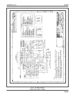
Page 42: ...SECTION 3 5 DDFP Page 37 Fig 13 DC Wiring Diagram Engines With Mechanical Guages ...

Page 43: ...DDFP Fig 14 DC Wiring Diagram Engines With Electrical Guages Page 38 SECTION 3 5 ...

Page 44: ...SECTION 3 5 DDFP Page 39 Fig 15 AC Wiring Diagram ...

Page 45: ...s Falk Long Term Grease LTG is highly recommended Sizes 1020T to 1090T10 are furnished with a pre measured amount of grease for each coupling The grease can be ordered for larger size couplings The use of general purpose grease requires re lubrication of the coupling at least annually Long Term Grease LTG The high centrifugal forces encountered in couplings separate the base oil and thickener of g...

Page 46: ...ISTENCY NLGI No 2 with 60 stroke worked penetration value in the range of 250 to 300 SEPARATION AND RESISTANCE Low oil separation rate and high resistance to separation from centrifuging LIQUID CONSTITUENT Possess good lubricating properties equivalent to a high quality well refined petroleum oil INACTIVE Must not corrode steel or cause swelling or deterioration of synthetic seals CLEAN Free from ...

Page 47: ...als with grease and place on shafts BEFORE mounting hubs Heat interference fit hubs as previously instructed Seal keyways to prevent leakage Mount hubs on their respective shafts so the hub face is flush with the end of its shaft unless otherwise indicated Tighten setscrews when furnished 2 Gap and Angular Alignment Use a spacer bar equal in thickness to the gap specified in Table 2 Page 5 Insert ...

Page 48: ...quipment is serviced disassemble the coupling and inspect for wear Replace worn parts Clean grease from coupling and repack with new grease Install coupling using new gasket as instructed in this manual Periodic Lubrication The required frequency of lubrication is directly related to the type of lubricant chosen and the operating conditions Steelflex couplings lubricated with common industrial lub...

Page 49: ...E For applications requiring greater misalignment refer application details to the Factory Angular misalignment is dimension X minus Y as illustrated below Parallel misalignment is distance P between the hub center lines as illustrated below End float with zero angular and parallel misalignment is the axial movement of the hubs s within the cover s measured from O gap SAE Grade 8 SAE Grade 8 SAE G...

Page 50: ...yle covers Sizes 1020T10 thru 1070T10 utilized socket head cap screws with captured locknuts The new style covers use hex head cap screws either inch or metric and unrestrained locknuts Specify either inch series SOCKET head or inch or metric series HEX head cap screws when ordering replacement parts PART NUMBERS 1 Seal T10 2 Cover T10 3 Hub Specify bore and keyway 4 Grid 5 Gasket T10 6 Fasteners ...

Page 51: ...a ving Clark e D D A During Start Up Inspection or when placing recon ditioned units into service some minor speed adjustments may be required It is recommended that this adjustment be performed by the authorized Detroit Diesel Distrib utor or Dealer representative The governor is located as follows I 53 Series at the upper left rear of engine I 71 Series at the upper right front of engine V Serie...

Page 52: ... R UN position during AUTOMATIC operation The controller will be una ble to stop the engine and O VERHEAT D AMAGE WILL RESULT Page 46 A 53 SERIES ENGINES Adjust the Gap by loosening the Lever Clamping Bolt Fig 3 and rotating the Run Stop Lever on the governor shaft to the desired position and re torque the clamping bolt Re check the gap and repeat adjustments if necessary After the check is comple...

Page 53: ...n the upper lever to 7 9 lb ft STEP 2 Adjust rod length so there is a def inite tightness when the manual operating handle passes through the straight outw ard position near the end of its CCW tra vel Tightness equals zero clearance shortened by tw o turns of one rod end STEP 3 Position the solenoids so the centerline of the slide pin equally divides the arc created by the mo vement of the lever p...

Page 54: ...tallation Operation Data Page DDFP 03DN DDFP 03DT DDFP L3DT DDFP T3DT DDFP L6FA DDFP T6FA DDFP 06FA DDFP 06FH DDFP L8FA DDFP 08FA DDFP 08FH DDFP 12FT DDFP 12FH Engine Model 43 Z 1 43 Z 1 43 Z 1 43 Z 1 43 Z 2 43 Z 2 43 Z 2 43 Z 2 43 Z 2 43 Z 2 43 Z 2 43 Z 3 43 Z 3 43 A 43 B 43 C 43 D 43 E 43 F 43 G 43 H 43 I 43 J 43 K 43 L 43 M SECTION 5 DDFP Page Engine Control Wiring Diagram DC 37 38 Engine Heate...

Page 55: ...J sec 27 28 33 35 45 47 52 55 56 59 58 61 61 64 Engine Radiated Heat Btu sec kJ sec 11 8 12 4 Heat Exchanger Minimum Flow 60 F Raw H2O gal min L min 4 5 17 5 0 19 6 23 6 5 25 7 0 26 7 5 28 8 0 30 95 F Raw H2O gal min L min 6 5 25 7 0 26 8 30 8 5 32 9 0 34 9 5 36 10 38 Heat Exchanger Maximum Cooling H2O Inlet Pressure lb in 2 kPa 20 138 Flow gal min L min 40 151 Thermostat Start to Open F C 170 77 ...

Page 56: ...ondary 10 Fuel Injector Timing in mm 1 490 37 846 Fuel Modulator Setting None Heater System All Speeds Jacket Water Heater Standard Wattage Nominal 1000 Voltage VAC 1P 115 Optional Voltage VAC 1P 230 Lube Oil Heater Required When Ambient Is Below 50 F 10 C Optional Wattage 125 Induction Air System Air Cleaner Type Indoors Service Only Washable Air Intake Restriction Maximum Limit Dirty Air Cleaner...

Page 57: ...ystem 1470 1760 2100 2350 2600 2800 3000 Engine H2O Heat Btu sec kJ sec 50 53 65 69 91 96 114 120 132 139 138 146 145 153 Engine Radiated Heat Btu sec kJ sec 11 8 12 4 Heat Exchanger Minimum Flow 60 F Raw H2O gal min L min 7 27 8 30 11 42 14 53 16 61 17 64 18 68 95 F Raw H2O gal min L min 9 34 10 38 13 49 16 61 18 68 19 72 20 76 Heat Exchanger Maximum Cooling H2O Inlet Pressure lb in 2 kPa 20 138 ...

Page 58: ...Clean Air Cleaner in H2O kPa 11 2 8 13 3 3 14 3 5 15 3 8 16 4 0 Engine Air Flow ft 3 min m3 min 405 11 445 13 480 14 502 14 515 15 Lubrication System All Speeds Oil Pressure normal lb in 2 kPa 40 70 276 433 In Pan Oil Temperature F C 230 245 110 118 Oil Pan Capacity High qt L 10 5 9 9 Low qt L 7 5 7 1 Total Oil Capacity with Filters qt L 12 5 11 8 Performance BMEP lb in 2 kPa 133 917 129 889 121 8...

Page 59: ...tion Drawing D 436 Cooling System 2600 2800 3000 Engine H2O Heat Btu sec kJ sec 169 178 175 185 178 188 Engine Radiated Heat Btu sec kJ sec 12 7 13 4 Heat Exchanger Minimum Flow 60 F Raw H2O gal min L min 21 79 22 83 22 83 95 F Raw H2O gal min L min 23 87 24 91 24 91 Heat Exchanger Maximum Cooling H2O Inlet Pressure lb in 2 kPa 20 138 Flow gal min L min 40 151 Thermostat Start to Open F C 170 77 F...

Page 60: ...Suction Clean System in H2O kPa 82 20 Dirty System in H2O kPa 164 40 Maximum Allowable Head on Fuel Pump ft m 5 0 1 5 Fuel Filter Micron Size Primary 30 Secondary 10 Fuel Injector Timing in mm 6840 1 520 38 608 Fuel Modulator Setting None Heater System All Speeds Jacket Water Heater Standard Wattage Nominal 1000 Voltage VAC 1P 115 Optional Voltage VAC 1P 230 Lube Oil Heater Required When Ambient I...

Page 61: ...2350 2600 2800 3000 Engine H2O Heat Btu sec kJ sec 61 64 79 83 111 117 141 149 170 179 179 189 195 205 Engine Radiated Heat Btu sec kJ sec 12 7 13 4 Heat Exchanger Minimum Flow 60 F Raw H2O gal min L min 9 0 34 10 38 14 53 18 68 21 79 22 83 24 91 95 F Raw H2O gal min L min 11 42 12 45 16 61 20 76 23 87 25 95 27 102 Heat Exchanger Maximum Cooling H2O Inlet Pressure lb in 2 kPa 20 138 Flow gal min L...

Page 62: ...or Setting None Heater System All Speeds Jacket Water Heater Standard Wattage Nominal 1000 Voltage VAC 1P 115 Optional Voltage VAC 1P 230 Lube Oil Heater Required When Ambient Is Below 50 F 10 C Optional Wattage 125 Induction Air System Air Cleaner Type Indoors Service Only Washable Air Intake Restriction Maximum Limit Dirty Air Cleaner in H2O kPa 13 3 3 15 3 8 16 4 0 17 4 3 18 4 5 Clean Air Clean...

Page 63: ...ation Drawing D 433 Cooling System 1470 1760 2100 2350 Engine H2O Heat Btu sec kJ sec 90 95 138 146 157 166 175 185 Engine Radiated Heat Btu sec kJ sec 42 44 Heat Exchanger Minimum Flow 60 F Raw H2O gal min L min 9 34 13 49 17 64 18 68 95 F Raw H2O gal min L min 14 53 17 64 23 87 25 95 Heat Exchanger Maximum Cooling H2O Inlet Pressure lb in 2 kPa 60 414 Flow gal min L min 50 189 Thermostat Start t...

Page 64: ...Injector Timing 9225 1 490 Fuel Modulator Setting None Heater System All Speeds Jacket Water Heater Standard Wattage Nominal 2500 Voltage VAC 1P 230 Optional Voltage VAC 1P 115 Lube Oil Heater Required When Ambient Is Below 50 F 10 C Optional Wattage 125 Induction Air System Air Cleaner Type Indoors Service Only Washable Air Intake Restriction Maximum Limit Dirty Air Cleaner in H2O kPa 6 5 1 7 7 0...

Page 65: ...ion Drawing D 433 Cooling System 1470 1760 2100 2350 Engine H2O Heat Btu sec kJ sec 145 153 170 179 180 190 206 217 Engine Radiated Heat Btu sec kJ sec 42 44 Heat Exchanger Minimum Flow 60 F Raw H2O gal min L min 11 42 14 53 18 68 20 76 95 F Raw H2O gal min L min 18 68 19 72 27 102 32 121 Heat Exchanger Maximum Cooling H2O Inlet Pressure lb in 2 kPa 60 414 Flow gal min L min 50 189 Thermostat Star...

Page 66: ... 1P 115 Lube Oil Heater Required When Ambient Is Below 50 F 10 C Optional Wattage 125 Induction Air System Air Cleaner Type Indoors Service Only Washable Air Intake Restriction Maximum Limit Dirty Air Cleaner in H2O kPa 6 5 1 7 7 0 1 8 8 0 2 0 9 0 2 3 Clean Air Cleaner in H2O kPa 4 5 1 1 5 0 1 3 6 0 1 5 7 0 1 8 Engine Air Flow ft 3 min m3 min 900 25 960 27 1050 30 1092 31 Maximum Allowable Tempera...

Page 67: ...kg 2325 1055 Installation Drawing D 433 Cooling System 1470 1760 2100 2350 Engine H2O Heat Btu sec kJ sec 206 217 233 246 260 274 284 300 Engine Radiated Heat Btu sec kJ sec 42 44 Heat Exchanger Minimum Flow 60 F Raw H2O gal min L min 13 49 21 79 26 98 28 106 95 F Raw H2O gal min L min 22 83 32 121 39 148 42 159 Heat Exchanger Maximum Cooling H2O Inlet Pressure lb in 2 kPa 60 44 Flow gal min L min...

Page 68: ...P 115 Lube Oil Heater Required When Ambient Is Below 50 F 10 C Optional Wattage 125 Induction Air System Air Cleaner Type Indoors Service Only Washable Air Intake Restriction Maximum Limit Dirty Air Cleaner in H2O kPa 6 5 1 7 7 0 1 8 8 0 2 0 9 0 2 3 Clean Air Cleaner in H2O kPa 4 5 1 1 5 0 1 3 6 0 1 5 7 0 1 8 Engine Air Flow ft 3 min m3 min 930 26 1120 32 1300 37 1425 40 Maximum Allowable Temperat...

Page 69: ...g 2355 1069 Installation Drawing D 433 Cooling System 1470 1760 2100 2350 Engine H2O Heat Btu sec kJ sec 188 198 228 241 247 261 250 264 Engine Radiated Heat Btu sec kJ sec 49 52 Heat Exchanger Minimum Flow 60 F Raw H2O gal min L min 14 53 23 87 28 106 29 110 95 F Raw H2O gal min L min 22 83 35 135 42 159 44 167 Heat Exchanger Maximum Cooling H2O Inlet Pressure lb in 2 kPa 60 414 Flow gal min L mi...

Page 70: ...ector Timing 7105 1 508 145 1 508 Fuel Modulator Setting None Heater System All Speeds Jacket Water Heater Standard Wattage Nominal 2500 Voltage VAC 1P 230 Optional Voltage VAC 1P 115 Lube Oil Heater Required When Ambient Is Below 50 F 10 C Optional Wattage 125 Induction Air System Air Cleaner Type Indoors Service Only Washable Air Intake Restriction Maximum Limit Dirty Air Cleaner in H2O kPa 6 5 ...

Page 71: ...ion Drawing D 433 Cooling System 1470 1760 2100 2350 Engine H2O Heat Btu sec kJ sec 275 290 312 329 376 397 439 463 Engine Radiated Heat Btu sec kJ sec 47 50 Heat Exchanger Minimum Flow 60 F Raw H2O gal min L min 40 151 48 182 56 212 64 242 95 F Raw H2O gal min L min 67 254 76 288 81 307 87 329 Heat Exchanger Maximum Cooling H2O Inlet Pressure lb in 2 kPa 20 138 Flow gal min L min 110 416 Thermost...

Page 72: ...r Timing 9225 1 490 Fuel Modulator Setting None Heater System All Speeds Jacket Water Heater Standard Wattage Nominal 2500 Voltage VAC 1P 230 Optional Voltage VAC 1P 115 Lube Oil Heater Required When Ambient Is Below 50 F 10 C Optional Wattage 150 Induction Air System Air Cleaner Type Indoors Service Only Washable Air Intake Restriction Maximum Limit Dirty Air Cleaner in H2O kPa 9 0 2 3 11 0 2 8 1...

Page 73: ...ooling System 1470 1760 2100 2350 Engine H2O Heat Btu sec kJ sec 249 263 283 299 340 359 397 419 Engine Radiated Heat Btu sec kJ sec 45 47 Heat Exchanger Minimum Flow 60 F Raw H2O gal min L min 36 136 43 163 51 193 58 220 95 F Raw H2O gal min L min 61 231 69 261 73 276 79 299 Heat Exchanger Maximum Cooling H2O Inlet Pressure lb in 2 kPa 60 44 Flow gal min L min 110 416 Thermostat Start to Open F C...

Page 74: ... Lube Oil Heater Required When Ambient Is Below 50 F 10 C Optional Wattage 150 Induction Air System Air Cleaner Type Indoors Service Only Washable Air Intake Restriction Maximum Limit Dirty Air Cleaner in H2O kPa 9 0 2 3 11 0 2 8 13 0 3 3 14 0 3 6 Clean Air Cleaner in H2O kPa 7 0 1 8 9 0 2 3 11 0 2 8 12 0 3 1 Engine Air Flow ft 3 min m3 min 1175 33 1375 39 1530 43 1620 46 Maximum Allowable Tempera...

Page 75: ...75 1111 Weight Dry lb kg 2605 1182 Wet lb kg 2793 1268 Installation Drawing D 433 Cooling System 1470 1760 2100 2350 Engine H2O Heat Btu sec kJ sec 296 312 317 334 371 391 396 418 Engine Radiated Heat Btu sec kJ sec 55 58 Heat Exchanger Minimum Flow 60 F Raw H2O gal min L min 39 148 42 159 48 182 52 197 95 F Raw H2O gal min L min 64 242 66 250 70 265 72 273 Heat Exchanger Maximum Cooling H2O Inlet...

Page 76: ...imum Allowable Head on Fuel Pump ft m 5 0 1 5 Fuel Filter Micron Size Primary 30 Secondary 12 Fuel Injector Timing 9225 1 490 Fuel Modulator Setting None Heater System All Speeds Jacket Water Heater Standard Wattage Nominal 2500 Voltage VAC 1P 230 Optional Voltage VAC 1P 115 Lube Oil Heater Required When Ambient Is Below 50 F 10 C Optional Wattage 150 Induction Air System Air Cleaner Type Indoors ...

Page 77: ... Btu sec kJ sec 264 279 308 325 331 349 Engine Radiated Heat Btu sec kJ sec 72 76 Heat Exchanger Minimum Flow 60 F Raw H2O gal min L min 26 98 29 110 37 140 95 F Raw H2O gal min L min 41 155 45 170 58 220 Heat Exchanger Maximum Cooling H2O Inlet Pressure lb in 2 kPa 60 414 Flow gal min L min 120 454 Thermostat Start to Open F C 177 81 Fully Open F C 197 92 Engine Coolant Capacity qt L 145 137 Cool...

Page 78: ... System All Speeds Jacket Water Heater Standard Wattage Nominal 4000 Voltage VAC 1P 230 Optional Voltage VAC 1P 460 Lube Oil Heater Required When Ambient Is Below 50 F 10 C Optional Wattage 300 Induction Air System Air Cleaner Type Indoors Service Only Washable Air Intake Restriction Maximum Limit Dirty Air Cleaner in H2O kPa 8 0 2 0 11 0 2 8 14 0 3 5 Clean Air Cleaner in H2O kPa 6 0 1 5 9 0 2 3 1...

Page 79: ...gine Radiated Heat Btu sec kJ sec 83 88 Heat Exchanger Minimum Flow 60 F Raw H2O gal min L min 32 121 36 136 46 174 56 21 95 F Raw H2O gal min L min 51 193 56 212 73 276 88 33 Heat Exchanger Maximum Cooling H2O Inlet Pressure lb in 2 kPa 60 414 Flow gal min L min 120 454 Thermostat Start to Open F C 177 81 Fully Open F C 197 92 Engine Coolant Capacity qt L 145 137 Coolant Pressure Cap lb in 2 kPa ...

Page 80: ...eater Required When Ambient Is Below 50 F 10 C Optional Wattage 300 Induction Air System Air Cleaner Type Indoors Service Only Washable Air Intake Restriction Maximum Limit Dirty Air Cleaner in H2O kPa 9 0 2 3 11 0 2 8 13 5 3 4 15 0 3 8 Clean Air Cleaner in H2O kPa 7 0 1 8 9 0 2 3 11 5 2 9 13 0 3 3 Engine Air Flow ft 3 min m3 min 1847 52 2197 62 2458 70 2580 73 Maximum Allowable Temperature Rise A...

Page 81: ...e Scraper with Expander Number per Piston 2 Sets Location Bottom of Skirt Piston Pin Type Crosshead Polished Hardened Air Cleaner Type Indoor Usage Only Oiled Fabric Pleats Material Surgical Cotton Aluminum Mesh Camshaft Material Forged Steel Location In Block Drive Gear Type of Cam Ground Camshaft Bearing End Journal Diameter 2 18 in 55 4 mm Length 1 50 in 38 1 mm Material SAE 799 Steel Back Cams...

Page 82: ...rome Faced Piston Rings Oil Type Double Scraper with Expander Number per Piston 2 Sets Location Bottom of Skirt Piston Pin Type Crosshead Polished Hardened Air Cleaner Type Indoor Usage Only Oiled Fabric Pleats Material Surgical Cotton Aluminum Mesh Camshaft Material Steel SAE 1513 Location In Block 1 Per Bank Drive Gear Type of Cam Ground Camshaft Bearing End Journal Diameter 1 50 in 38 0 mm Leng...

Page 83: ... Piston Rings Oil Type Double Scraper with Expander Number per Piston 2 Sets Location Bottom of Skirt Piston Pin Type Crosshead Polished Hardened Air Cleaner Type Indoor Usage Only Oiled Fabric Pleats Material Surgical Cotton Aluminum Mesh Camshaft Material Steel SAE 1513 Location In Block 1 Per Bank Drive Gear Type of Cam Ground Camshaft Bearing End Journal Diameter 1 50 in 38 0 mm Length 2 12 in...

Page 84: ...d adequate supporting records But what about YOU the user of this equipment You have nei ther the time nor the inclination to search for specif ic part number data Detroit Diesel s Distrib utor Dealer organiza tion stands ready to meet your needs When you contact the Distributor Dealer provide the follo wing data from the engine data place at the left front of the engine Model Number _____________...

Page 85: ...ement With K N 99 0516 Oil Before Use Do Not Use Element Dry NOTE SOME ENGINES REQ UIRE TWO OIL FILTERS ANALYSIS PROGRAM Analysis Kits are currently available through your local DDC Distributor These kits can be purchased for a nominal fee to give each DDFP user the capability of taking oil or coolant samples and mailing them to a testing laboratory By a series of laboratory test the y can determi...

Page 86: ...r problem originates with a dealer explain the matter to a management member of the distrib utorship with whom the dealer has his service agreement Step 2 When it appears that your problem cannot be resolved at the Distrib utor le vel without additional assis tance contact Clarke Detroit Diesel Allison 3133 E Kemper Road Cincinnati OH 45241 Attention Fire Pump Service Manager Phone 513 771 2200 Ex...

Page 87: ...weg CH 2557 Studen Switzerland Phone 41 32 215 629 Latin American Region 2277 N W 14th St Latin American Bldg Miami Florida 33125 0068 Phone 305 637 1555 Eastern Region 187 Monmouth Park Hwy West Long Branch New Jersey 07704 Phone 908 222 1888 Southeastern Region 5111 Bowden Rd Jacksonville Florida 32216 Phone 904 448 8833 Central Region 13400 Outer Drive West Detroit Michigan 48239 4001 Phone 313...

Page 88: ...ference is to Detroit Diesel or Canada Limited This Warranty Does Not Cover Repairs Due To Accidents Misuse Storage Damage Negligence Or Certain Modifications Repairs due to an accident misuse misapplication storage damage negli gence or modif ication exceeding DDC specif ications are not co vered by this warranty Engine Removal And Reinstallation Labor and material costs for engine remo val and r...

Page 89: ... the engine is restricted to 250 hours or less within 12 months from the date of sale to the f irst user the warranty will be e xtended to the second year of operation pro viding that the combined total use does not exceed 500 hours Low usage extended warranty does not apply to 100 Series or 200 Series engines 6 Long Storage The standard warranty allows for a maximum of 12 months storage before sa...

Page 90: ...or air circulation The stored engine should be inspected periodi cally for ob vious conditions such as standing w ater part theft excess dirt buildup or any other condition that may be detrimental to the engine or components Any such condi tions found must be corrected immediately If a situation arises that e xtended storage is una voidable beyond six months it may be necessary to contact your loc...

Page 91: ...verspeed 10 Engine Rotation 7 Engine Start Up 8 Engine Tune Up 42 Electrical System 31 Exhaust Gas Temp Volume 43 Exhaust Operation 19 F Filters Fuel 13 44 Lubricating Oil 22 Air Cleaner 16 Firing Order 7 Fuel Specifications 13 Fuel System Operation 12 Check Valve 12 Injector 12 Pump 12 System Schematic 14 Maintenance Service 15 G General Description 2 General Specifications 6 Governor Engine 14 4...

Page 92: ...Raw Water Cooling Loop 29 Raw Water Flow Requirements 43 Rotation 3 S Standard Model Views 9 Serial Number 5 Service Assistance 46 Shutdown Systems 33 Subject Page Subject Page Specifications Fuel 13 General 6 Lubrication Oil 22 Speed Adjustment 42 Speed Switch 10 33 Starting System Electric 34 Solenoid Governor 33 Storage Extended 49 T Tachometer 33 Thermostat 28 Tune Up Procedures 42 Technical D...

Reviews: