8
START UP, ADJUSTMENT
AND SAFETY CHECK
1. Furnace must have a 120 V power supply properly
connected and grounded (NOTE: Proper polarity
must be maintained for 120 V wiring. Control status
indicator light flashes rapidly and furnace does not
operate if polarity is incorrect.)
2. Thermostat wire connections at terminals R, W/W1,
G, Y/Y2, etc. must be made at 24 V terminal block
on furnace control
3. Natural gas service pressure must not exceed 0.38
psig (10.5 in. w.c.), but must be no less than 0.16
psig (4.5-in. w.c.). Propane service pressure must
dot exceed 0.47 psig (13 in. w.c.) but must be no
less than 0.40 psig (11 in. w.c.) Refer to table 4 or
furnace rating plate.
4. Blower door must be in place to complete 120 V
electrical circuit to furnace.
8.1
Starting the furnace
This appliance is equipped with a hot surface ignition
device. This device lights the main burners each time
the room thermostat calls for heat.
See the lighting
instructions on the furnace.
During initial start-up, it is not unusual for odour or smoke
to come out of any room registers. To ensure proper
ventilation, it is recommended to open windows and
doors before initial firing.
The furnace has negative pressure switch that is a safety
during a call for heat. The induced draft blower must pull
a negative pressure on the heat exchanger to close the
negative pressure switch. The induced draft blower must
maintain at least the negative pressure switch set point
for the furnace to operate. If the induced draft blower fails
to close or maintain the closing of the negative pressure
switch, an error code would result.
Follow those step to properly start the furnace:
1. Remove the burner compartment control access
door.
2.
IMPORTANT
Be sure that the manual gas control
has been in the «off» position for at least five
minutes. Do no attemps to manually light the main
burners.
3. Set the thermostat to it lowest setting and turn off
furnace electrical power.
4. Replace the burner compartment control access
door.
WARNING
Failure to replace the burner door can cause
products of combustion to be released into
the conditioned area resulting in personal
injury or death.
5. Turn on the manual gas stop.
6. Turn on the furnace electrical power.
7. Put thermostat to «Heat» mode and set at least
10°F above room temperature.
8. After the burner are lit, set the room thermostat to
desired temperature.
These furnaces are equipped with a manual reset limit
switch in burner assembly. This switch opens and shuts
off power to the gas valve if an overheat condition (flame
rollout) occurs in burner assembly.
Correct inadequate combustion-air supply or improper
venting condition before resetting switch.
DO NOT
jumper this switch.
Before operating furnace, check
flame rollout manual reset switch for continuity.
If
necessary, press de button to reset switch.
9
SINGLE STAGE X13 MOTOR
ECM
Furnaces with model number CXX-1-X are equipped with
a fixed torque ECM motor. This motor provides ease in
adjusting the blower speeds in cooling or heating mode.
Blowers should be adjusted by the installer to match
the installation requirements so as to provide the correct
heating temperature rise and cooling load.
9.1
Selecting blower speed
To adjust the circulator blower speed, proceed as follow:
1. Turn off the power to the furnace
2. Select the heating and cooling blower speeds that
match the installation requirements from the tables
below.
3. Relocate the desired motor leads to the desired
torque tap on the motor. The red wire locate the
heating speed and the blue wire locate de cooling
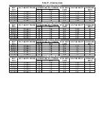
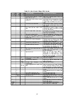
speed. Refer to tables 10 to 14 for tap details.
4. If heating and cooling speeds use the same speed,
a jumper wire must be used between the heat and
cool terminal on the motor.
5. Turn on power to the furnace.
6. Verify
proper
temperature
rise.
Excessive
temperature rise can cause limit switch tripping.
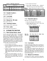
26
Summary of Contents for C105-1-D
Page 24: ...Figure 26 Alternate horizontal termination C Figure 27 Venting gasket 23...
Page 25: ...Figure 28 Direct vent clearance 24...
Page 26: ...Figure 29 Other than Direct vent clearance 25...
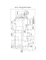
Page 34: ...Figure 32 Single Stage PSC Wiring diagram...
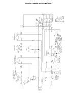
Page 35: ...Figure 33 Two Stage PSC Wiring diagram...
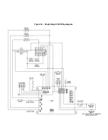
Page 36: ...Figure 34 Single Stage ECM Wiring diagram...
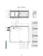
Page 39: ...Figure 35 Dimensions 38...
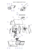
Page 40: ...Figure 36 Exploded view CXX 1 X part 1...
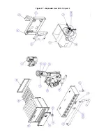
Page 41: ...Figure 37 Exploded view CXX 1 X part 2...
Page 43: ...Figure 38 Exploded view Cxx 1 D part 1...
Page 44: ...Figure 39 Exploded view Cxx 1 D part 2...
Page 46: ...Figure 40 Exploded view Cxx 2 D part 1...


