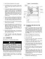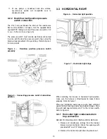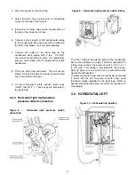
in series with the low fire pressure switch (top) using the
brown jumper furnished in the parts bag. Refer to figure
12 for more details.
3.5
MULTIPOSITION VENTING
DRAINAGE
All furnaces with horizontal exhaust vent piping must
have drain tee assembly and trap installed in the exhaust
pipe as close to the furnace as possible. See Figures 3,
6 and 10.
4
DUCT INSTALLATION
4.1
GENERAL REQUIREMENTS
The duct system should be designed and sized according
to accepted national standards such as those published
by: Air Conditioning Contractors Association (ACCA),
Sheet Metal and Air Conditioning Contractors National
Association (SMACNA) or American Society of Heating,
Refrigerating and Air Conditioning Engineers (ASHRAE).
Consult The Air Systems Design Guidelines reference
tables available at your local distributor.
The duct system should be sized to handle the required
system design aiflow at the design external static
pressure. When a furnace is installed so that the supply
ducts carry air circulated by the furnace to areas outside
the space containing the furnace, the return air shall also
be handled by duct(s) sealed to the furnace casing and
terminating outside the space containing the furnace.
This furnace may be installed, with a two pipe sealed
combustion configuration (direct vent), in a space utilized
as part of the return air supply. A filter must be installed
in the return opening of the furnace and a grill should be
installed in the space to allow proper circulation of air.
Secure ductwork with proper fasteners for type of
ductwork used. Seal supply and return duct connections
to the furnace with code approved tape or duct sealer.
Ductwork passing through an unconditioned space
should be insulated to enhance system performance.
When air conditioning is used, a vapour barrier is
recommended.
Maintain a 1 in. (25 mm) clearance from combustible
materials to supply air ductwork for a distance of 36 in.
(914 mm) horizontally from the furnace. See NFPA 90B
or local code for further requirements.
Flexible connections can be used between ductwork and
furnace to prevent transmission of vibration.
Many states, provinces and localities are considering
or have implemented standards and/or restrictions on
duct sizing practices, ductwork leakage, and/or ductwork
thermal, airflow and electrical efficiencies.
CONSULT
LOCAL CODE OFFICIALS for ductwork design and
performance requirement in your area.
4.2
DUCT EXTERNAL STATIC
PRESSURE
Higher than prescripted static pressure will decrease the
air flow, causing excessive temperature rise, opening of
the thermodisk, failure of the heat exchanger and / or
poor performance of the heat pump / air conditioning.
To measure total external static pressure, proceed as
follow:
1. Run the furnace at the system maximum airflow
2. Return duct : Make sure the furnace filter is clean
and measure the static pressure between the filter
and the inlet of the furnace (negative pressure
reading)
3. Supply duct : Measure the static pressure between
the furnace and the cooling coil (positive static
pressure). Tape up the hole when test is complete.
4. Substract the inlet pressure from the supply
pressure. For exemple, if you measured 0.3"w.c.
in the supply and -0.2" in the return:
0.3"w.c. - (-0.2"w.c.) = 0.5"w.c.
If the total external static pressure exceeds the maximum
listed on the furnace rating plate, check for closed
dampers, register, unproperly size duct work or incorrect
dipswitch settings. Make sure the temperature rise is
coherent with the furnace rating plate.
4.3
RETURN AIR CONNECTIONS
The return air duct must be connected to the bottom, left
side or right side. If necessary (depending on your filter
restriction), provision should be made for a double return.
In downflow configuration, side return air is not permitted,
it must be connected to bottom.
Connection to the back of the furnace is prohibited.
Static pressure in the return air duct should be -0.2"w.c.
at system maximum airflow.
To avoid high noise level from the return side of the unit,
return duct shall have at least two 90° elbows and 10 ft
of straight duct.
4.3.1
Bottom return
Cut a rectangular opening on the bottom plate of the
furnace using the knock-outs.
In Upflow orientation when using the bottom inlet, return
air base can be used. This base allows the connection
of the duct on the side with a bottom inlet. See tables
29, 30 and 31 for the part number corresponding to your
furnace.
13
Summary of Contents for C105-1-D
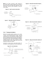
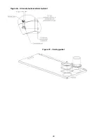
Page 24: ...Figure 26 Alternate horizontal termination C Figure 27 Venting gasket 23...
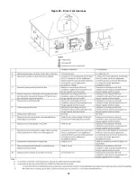
Page 25: ...Figure 28 Direct vent clearance 24...
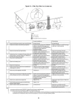
Page 26: ...Figure 29 Other than Direct vent clearance 25...
Page 34: ...Figure 32 Single Stage PSC Wiring diagram...
Page 35: ...Figure 33 Two Stage PSC Wiring diagram...
Page 36: ...Figure 34 Single Stage ECM Wiring diagram...
Page 39: ...Figure 35 Dimensions 38...
Page 40: ...Figure 36 Exploded view CXX 1 X part 1...
Page 41: ...Figure 37 Exploded view CXX 1 X part 2...
Page 43: ...Figure 38 Exploded view Cxx 1 D part 1...
Page 44: ...Figure 39 Exploded view Cxx 1 D part 2...
Page 46: ...Figure 40 Exploded view Cxx 2 D part 1...


