WARNING
Corrosive or contaminated air may cause failure
of parts containing flue gas, which could leak into
the living space.
Air for combustion must not
be contaminated by halogen compounds, which
include fluoride, chloride, bromide and iodide.
These elements can corrode the heat exchanger
and burner cabinet component. This conditions
would shorten the furnace life. Air contaminants
are found in aerosol sprays, detergents, bleaches,
cleaning solvents, salts, air fresheners, and other
household products. Do not install the furnace
in a corrosive or contaminated atmosphere.
Make sure all combustion and circulating air
requirements are met, in addition to all local codes
and ordinances.
7.1
GENERAL
These furnaces are certified as either direct vent (two
pipe) or non-direct vent (single pipe).
If this furnace replaces a furnace that was connected to
a vent system or chimney, the vent may need to be re-
sized.
An abandoned masonry chimney may be used as a
raceway for properly insulated and supported combustion
air (when applicable) and vent pipes.
If more than
one furnace is installed, they must have their own set
of combustion air and vent pipes and be terminated
individually. Other gas appliances with their own venting
system may also use the abandoned chimney as a
raceway providing it is permitted by local code, the
current edition of the National Fuel Gas Code and the
vent or liner manufacturer’s installation instructions. Care
must be taken to prevent the exhaust gases of one
appliance from contaminating the combustion air of other
gas appliances. Do not take combustion air from inside
the chimney when using ventilated combustion air or
single pipe vent option.
For Canadian Installations, field supplied PVC venting
materials must be UL S636 listed. This requirement does
not apply to the combustion air pipe.
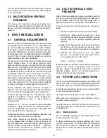
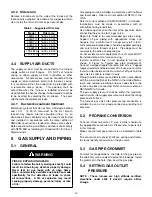
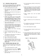
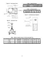
Below are important information that needs to be
considered when installing the venting system:
• The vent pipe and combustion air pipe must of be
the same diameter.
• Slope horizontal vent piping upward a minimum
of 1/4" per foot of run so that condensate drains
toward the furnace.
• Support horizontal vent piping at least every five
feet. No sags or dips are permitted.
• The vent pipe and combustion air pipe must
terminate on the same building side.
• Provide the space with sufficient air for proper
combustion using permanent pipe (direct-vent)
or opening(s) directly communicating with the
outdoors (non directe vent).
• Insulate all vent runs through unconditioned
spaces where below-freezing temperatures are
expected with 1" thick medium-density, foil-faced
fiberglass. (In Canada, per the vent manufacturer’s
instructions)
• For runs where condensate could accumulate and
freeze (including vent termination), wrap the vent
pipe with self-regulating 5 Watt heat tape. The heat
tape must be U.L./CSA. listed and installed per the
manufacturer’s instructions.
• The combustion air and exhaust terminations must
be at least 12” above grade/expected level of snow.
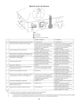
• Ensure the location of the combustion air inlet with
respect to the exhaust vent terminal complies with
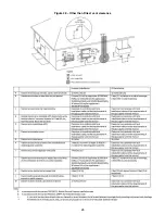
Figure 28 and local codes.
7.2
DIRECT VENT
When this furnace is installed as a direct vent (2 pipes)
furnace, no special provisions for combustion air are
required.
Direct vent installations require a dedicated combustion
air and exhaust vent piping. The system is only using
outside air for combution.
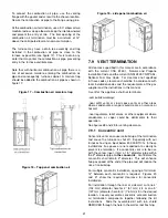
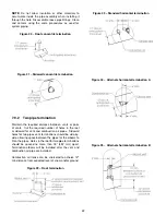
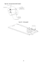
The vent and combustion air pipe can terminate vertically,
through the roof or horizontaly through and outside wall.
Refer to figures for approved termination.
Penetration throught a roof requires appropriate sealing
and proper flashing.
In Canada
, refer to manufacturer’s instructions for
supporting ULC S636 venting. ABS can be used for the
combustion air pipe.
7.3
NON DIRECT VENT
All air for combustion comes directly to the furnace from a
space that is well ventilated with outdoor air (such as an
attic or crawlspace). In addition, other gas appliances
installed in the space with the furnace may require
outside air for combustion.
The combustion air pipe
cannot be terminated in attics or crawlspaces that uses
ventilation fans designed to operate during the heating
season. If ventilation fans are present in these areas, the
combustion pipe must terminate outdoors as a direct vent
(2 pipe) system.
18
Summary of Contents for C105-1-D
Page 24: ...Figure 26 Alternate horizontal termination C Figure 27 Venting gasket 23...
Page 25: ...Figure 28 Direct vent clearance 24...
Page 26: ...Figure 29 Other than Direct vent clearance 25...
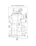
Page 34: ...Figure 32 Single Stage PSC Wiring diagram...
Page 35: ...Figure 33 Two Stage PSC Wiring diagram...
Page 36: ...Figure 34 Single Stage ECM Wiring diagram...
Page 39: ...Figure 35 Dimensions 38...
Page 40: ...Figure 36 Exploded view CXX 1 X part 1...
Page 41: ...Figure 37 Exploded view CXX 1 X part 2...
Page 43: ...Figure 38 Exploded view Cxx 1 D part 1...
Page 44: ...Figure 39 Exploded view Cxx 1 D part 2...
Page 46: ...Figure 40 Exploded view Cxx 2 D part 1...

