7.4
SPECIAL VENTING
REQUIREMENTS FOR
INSTALLATION IN CANADA
In Canada, S636 certified primers and cements must
be used and be of the same manufacturer of the S636
venting system. Do not mix primers and cements from
one manufacturer with a vent system from a different
manufacturer. Follow the manufacturer’s instructions for
the use of primer and cement and never use primer or
cement beyond its expiration date.
All fire stop and roof flashing used with this system must
be UL listed material.
Acceptability under Canadian standard CAN/CSA B149
requires full compliance with all installation instructions.
The
authority
having
jurisdiction
(gas
inspection
authority, municipal building department, fire department,
etc.) should be consulted before installation to determine
the need to obtain a permit.
7.5
MATERIAL
USA:
Combustion air and vent pipe, fittings, primers and
solvents must conform to American National Standard
Institute (ANSI) and American Society for Testing and
Material (ASTM) and be of the same manufacturer. See
table 7
Table 7 – Approved Vent and Combustion air pipe
material USA installation
Material
Standards
PVC - DWV
ANSI/ASTM D2265
PVC schedule 40
ANSI/ASTM D1785
CPVC Schedule 40
ANSI/ASTM F441
SDR-21, SDR-26-26 PVC
ANSI/ASTM D2241
ABS-DWV Schedule 40
ANSI/ASTM D2661
Stainless steel (SS)
UL-1738
Polypropylene (PP)
UL-1738
and
ULC-
S636
All vent piping and combustion air piping MUST
conform to local and national codes.
Pipe cement must be PVC (ANSI/ASTM D2564) or
CPVC (ANSI/ASTM F493).
Primers must be PVC/CPVC (ANSI/ASTM F656).
CANADA:
Vent pipe installations in Canada must conform to
the requirements of CAN/CSA B149 code.
PVC and
CPVC vent systems must be composed of pipe, fittings,
cements, and primers listed to ULC S636 and must be of
the same manufacturer.
Combustion air pipe can use ABS material meeting the
ASTM standard D2661 / CSA B181.1.
All vent piping and combustion air piping MUST conform
to local and national codes.
7.6
SIZE THE VENT AND
COMBUSTION AIR PIPES
Furnace combustion air and vent pipe connections are
sized for 2” pipe. Any pipe diameter change should be
made outside furnace casing in a vertical section of the
pipe. Any change in diameter to the pipe must be made
as close to the furnace as reasonably possible.
The maximum allowable vent length for the vent and
combustion air pipe (when used) is listed in table 8 and
depends on the furnace input.
The maximum length
must include straight pipe and any fitting and termination.
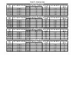
Equivalent length of various fitting is list in table 9.
A minimum linear length of 5 ft must be respected.
To properly measure the Equivalent Vent Length :
1. Measure the linear pipe distance from the furnace
to the termination for each pipe.
2. Count the number of elbows for each pipe.
3. For each pipe, multiply the number of elbows by the
equivalent length for the type of elbow used (see
table 9). Record the equivalent length of all the
elbows for each pipe.
4. Record the equivalent length of the termination
used (see table 9 ).
5. Add the equivalent length of the elbows and
termination to the linear distance measured for
each pipe.
6. If the calculated vent length is greater than the
maximum allowed vent length (for either vent pipe
or combustion air pipe), consider modifying the
termination location or use a greater pipe diameter.
19
Summary of Contents for C105-1-D
Page 24: ...Figure 26 Alternate horizontal termination C Figure 27 Venting gasket 23...
Page 25: ...Figure 28 Direct vent clearance 24...
Page 26: ...Figure 29 Other than Direct vent clearance 25...
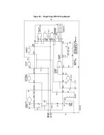
Page 34: ...Figure 32 Single Stage PSC Wiring diagram...
Page 35: ...Figure 33 Two Stage PSC Wiring diagram...
Page 36: ...Figure 34 Single Stage ECM Wiring diagram...
Page 39: ...Figure 35 Dimensions 38...
Page 40: ...Figure 36 Exploded view CXX 1 X part 1...
Page 41: ...Figure 37 Exploded view CXX 1 X part 2...
Page 43: ...Figure 38 Exploded view Cxx 1 D part 1...
Page 44: ...Figure 39 Exploded view Cxx 1 D part 2...
Page 46: ...Figure 40 Exploded view Cxx 2 D part 1...

