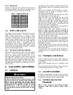
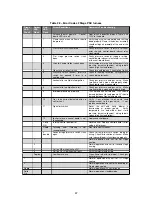

Table 17 – Error codes single stage
LED
Desription
1 flash, pause
System Lockout
2 flash, pause
Pressure switch stuck
close
3 flash, pause
Pressure switch stuck
open
4 flash, pause
Open limit switch
5 flash, pause
Open rollout switch
6 flash, pause
115VAC polarity
7 flash, pause
Low flame sense
continuous
flashing
Flame
has
been
sensed when no flame
should be present
10
SINGLE
STAGE
PSC
MOTOR
Furnaces with model number CXX-1-D are equipped
with a fixed speed motor. This motor provides ease in
adjusting the blower speeds in cooling or heating mode.
Blowers should be adjusted by the installer to match
the installation requirements so as to provide the correct
heating temperature rise and cooling load.
10.1
Selecting the blower speed on
PSC motor
These blower speeds are set for a temperature rise
of 55°F at normal static pressure.
Blowers should
be adjusted by the installer to match the installation
requirements so as to provide the correct heating
temperature rise and cooling load.
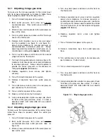
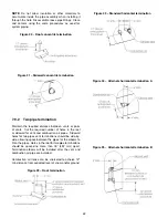
To adjust the
circulator blower speed, proceed as follow:
1. Turn off the power to the furnace
2. Select the heating and cooling blower speeds that
match the installation requirements.
3. Relocate the desired motor leads to the desired
speed on the motor. The red wire locate the heating
speed and the blue wire locate de cooling speed.
4. If heating and cooling speeds are the same, a
jumper wire must be used between the heat and
cool terminal on the control board. The unused
leads must be connected to the “PARK” terminal on
the control board.
5. Turn on power to the furnace.
6. Verify
proper
temperature
rise.
Excessive
temperature can cause limit switch tripping.
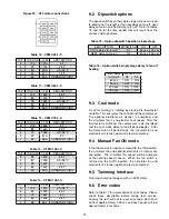
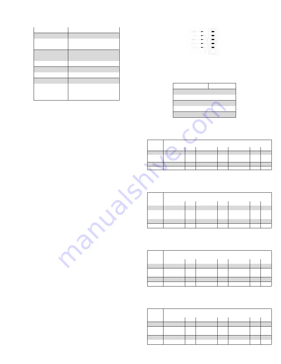
Figure 31 – PSC motor connections
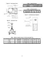
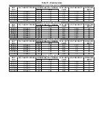
Table 18 – Suggested heating fan speed on single
stage furnace
INPUT BTU/hr
SPEED
45 000
LOW
60 000
MED-LOW
75 000
MED-LOW
105 000
HIGH
120 000
HIGH
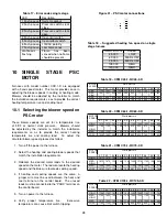
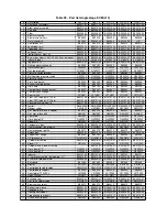
Table 19 – CFM C45-1-D/C45-2-D
MOTOR
SPEED
Static pressure
0.1
0.2
0.3
0.4
0.5
0.6
0.7
0.8
0.9
1.0
HIGH
1120
1095
1045
1020
970
915
845
780
710
640
MED-
HIGH
1047
1045
980
940
880
835
775
715
665
585
MED
935
950
910
865
820
780
730
670
600
565
LOW
930
925
875
835
800
760
710
660
605
545
Table 20 – CFM C60-1-D/C60-2-D
MOTOR
SPEED
Static pressure
0.1
0.2
0.3
0.4
0.5
0.6
0.7
0.8
0.9
1.0
HIGH
1374 1372 1370 1305 1230 1155 1085 1005 945
860
MED-
HIGH
1198 1195 1134 1085 1025 975
925
875
814
740
MED
1155 1150 1100 1050 1000 955
905
860
795
725
LOW
1026 1005 980
945
905
865
820
780
720
655
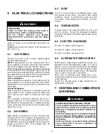
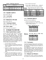
Table 21 – CFM C75-1-D/C75-2-D
MOTOR
SPEED
Static pressure
0.1
0.2
0.3
0.4
0.5
0.6
0.7
0.8
0.9
1.0
HIGH
1617 1615 1540 1440 1355 1280 1204 1182 1060 980
MED-
HIGH
1675 1670 1590 1480 1382 1300 1219 1192 1065 982
MED
1500 1496 1388 1289 1188 1133 1087 1083 1015 975
LOW
1272 1197 1148 1108 1042 967
913
824
777
749
Table 22 – CFM C105-1-D/C105-2-D
MOTOR
SPEED
Static pressure
0.1
0.2
0.3
0.4
0.5
0.6
0.7
0.8
0.9
1.0
HIGH
1748 1740 1615 1515 1430 1355 1285 1195 1110 1030
MED-
HIGH
1700 1655 1550 1435 1360 1285 1230 1150 1080 990
MED
1415 1405 1325 1240 1180 1135 1070 1005 930
845
LOW
1165 1130 1065 1025 975
935
870
830
775
705
28
Summary of Contents for C105-1-D
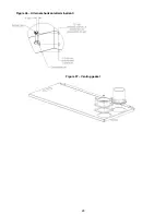
Page 24: ...Figure 26 Alternate horizontal termination C Figure 27 Venting gasket 23...
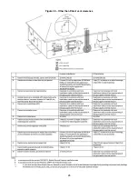
Page 25: ...Figure 28 Direct vent clearance 24...
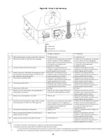
Page 26: ...Figure 29 Other than Direct vent clearance 25...
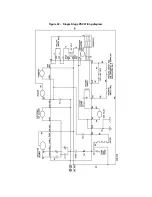
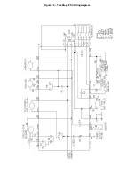
Page 34: ...Figure 32 Single Stage PSC Wiring diagram...
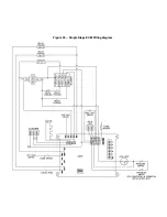
Page 35: ...Figure 33 Two Stage PSC Wiring diagram...
Page 36: ...Figure 34 Single Stage ECM Wiring diagram...
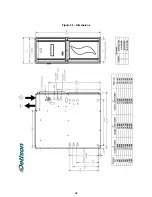
Page 39: ...Figure 35 Dimensions 38...
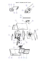
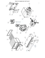
Page 40: ...Figure 36 Exploded view CXX 1 X part 1...
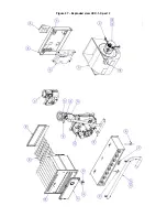
Page 41: ...Figure 37 Exploded view CXX 1 X part 2...
Page 43: ...Figure 38 Exploded view Cxx 1 D part 1...
Page 44: ...Figure 39 Exploded view Cxx 1 D part 2...
Page 46: ...Figure 40 Exploded view Cxx 2 D part 1...


