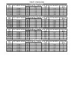
Table 27 – Electrical data
Single Stage X13 motor
UNIT
VOLT-HERTZ-PHASE
OPERATING VOLT RANGE
MAX UNIT
UNIT AMPACITY
BREAKER
SIZE
MAX
MIN
AMPS
AMPS
45 000
120-60-1
127
104
10.2
11.9
15
60 000
120-60-1
127
104
10.2
11.9
15
75 000
120-60-1
127
104
11.4
13.5
15
105 000
120-60-1
127
104
13.9
16.6
20
120 000
120-60-1
127
104
13.9
16.6
20
Single Stage PSC motor
UNIT
VOLT-HERTZ-PHASE
OPERATING VOLT RANGE
MAX UNIT
UNIT AMPACITY
BREAKER
SIZE
MAX
MIN
AMPS
AMPS
45 000
120-60-1
127
104
13.4
15.9
20
60 000
120-60-1
127
104
13.4
15.9
20
75 000
120-60-1
127
104
13.1
15.5
20
105 000
120-60-1
127
104
16.4
19.7
20
120 000
120-60-1
127
104
16.4
19.7
20
Two Stage ECM motor
UNIT
VOLT-HERTZ-PHASE
OPERATING VOLT RANGE
MAX UNIT
UNIT AMPACITY
BREAKER
SIZE
MAX
MIN
AMPS
AMPS
45 000
120-60-1
127
104
10.7
12.7
15
60 000
120-60-1
127
104
12.6
15
15
75 000
120-60-1
127
104
12.6
15
15
105 000
120-60-1
127
104
15.8
19
20
120 000
120-60-1
127
104
15.8
19
20
Two Stage PSC motor
UNIT
VOLT-HERTZ-PHASE
OPERATING VOLT RANGE
MAX UNIT
UNIT AMPACITY
BREAKER
SIZE
MAX
MIN
AMPS
AMPS
45 000
120-60-1
127
104
12.8
15.3
20
60 000
120-60-1
127
104
12.8
15.3
20
75 000
120-60-1
127
104
12.5
15.0
15
105 000
120-60-1
127
104
15.8
19.1
20
120 000
120-60-1
127
104
15.8
19.1
20
32
Summary of Contents for C105-1-D
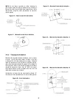
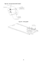
Page 24: ...Figure 26 Alternate horizontal termination C Figure 27 Venting gasket 23...
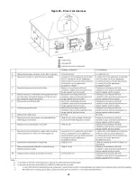
Page 25: ...Figure 28 Direct vent clearance 24...
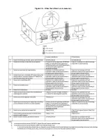
Page 26: ...Figure 29 Other than Direct vent clearance 25...
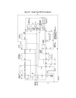
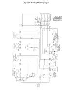
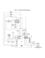
Page 34: ...Figure 32 Single Stage PSC Wiring diagram...
Page 35: ...Figure 33 Two Stage PSC Wiring diagram...
Page 36: ...Figure 34 Single Stage ECM Wiring diagram...
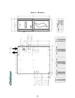
Page 39: ...Figure 35 Dimensions 38...
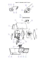
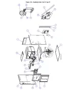
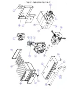
Page 40: ...Figure 36 Exploded view CXX 1 X part 1...
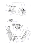
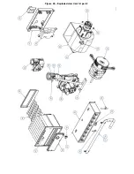
Page 41: ...Figure 37 Exploded view CXX 1 X part 2...
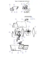
Page 43: ...Figure 38 Exploded view Cxx 1 D part 1...
Page 44: ...Figure 39 Exploded view Cxx 1 D part 2...
Page 46: ...Figure 40 Exploded view Cxx 2 D part 1...

