3. Supply duct : Measure the static pressure between
the furnace and the cooling coil (positive static
pressure). Tape up the hole when test is complete.
4. Substract the inlet pressure from the supply
pressure. For exemple, if you measured 0.3"w.c.
in the supply and -0.2" in the return:
0.3"w.c. - (-0.2"w.c.) = 0.5"w.c.
If the total external static pressure exceeds the maximum
listed on the furnace rating plate, check for closed
dampers, register, unproperly size duct work or incorrect
dipswitch settings. Make sure the temperature rise is
coherent with the furnace rating plate.
5.3
SMART DUCT SYSTEM
Dettson Industries also offers the Smart Duct System.
Please refer to the Smart Duct Manual (X40240) for
proper installation of this system.
Please note Smart Duct system can only be used with
approuved Smart Duct furnaces.
5.4
RETURN AIR CONNECTIONS
The return air duct must be connected to the bottom or
back side. Avoid front side, since it is the only panel
giving access to the blower and motor.
In downflow configuration, side return air is not permitted,
it must be connected to bottom.
Static pressure in the return air duct should be -0.2"w.c.
at system maximum airflow.
5.5
SUPPLY AIR DUCTS
The supply air duct must be connected to the furnace
supply outlet air duct flanges.
DO NOT cut furnace
casing to attach supply air duct, humidifier, or other
accessories. All accessories must be connected to the
supply or return ductwork, external to furnace’s casing.
It is recommend that the outlet duct be provided with
a removable access panel.
This opening shall be
accessible when the furnace is installed and shall be
sized to allow the heat exchanger to be viewed or a probe
to be inserted for sampling the air stream. The cover
attachement should prevent leaks.
5.5.1
Ductwork acoutiscal treatment
Metal duct systems that do not have a 90 degree elbow
and 10 ft.
(3 M) of main duct to the first branch
take-off may require internal acoustical lining.
As an
alternative, fibrous ductwork may be used if constructed
and installed in accordance with the latest edition of
SMACNA construction standard on fibrous glass ducts.
Both acoustical lining and fibrous ductwork shall comply
with NFPA 90B as tested by UL Standard 181 for Class 1
Rigid air ducts.
6
GAS SUPPLY AND PIPING
6.1
GENERAL
Use a back-up wrench on the inlet of the gas valve when
connecting the gas line to the gas valve.
Report to Table 5 for recommended gas pipe sizing.
Support all gas piping with appropriate straps and
hangers. Use a minimum of 1 hanger every 6 ft (1.8 m).
Joint compound (pipe dope) should be applied sparingly
and only to male threads of joints. Pipe dope must be
resistant to the action of propane gas.
An accessible manual equipment shut off valve MUST be
installed external to furnace casing.
Install a sediment trap in riser leading to furnace.
Connect a capped nipple into lower end of tee.
Install a union between the manual shut off gas and the
gas valve in order to remove it easily.
Piping should be pressure and leak tested in accordance
with the current edition of the NFGC in the United States,
local, and national plumbing and gas codes before the
furnace has been connected. Refer to current edition of
NSCNGPIC in Canada.
The gas supply pressure shall be within the maximum
and minimum inlet supply pressures marked on the rating
plate and in Table 3.
The furnace gas valve inlet pressure tap connection is
suitable to use as test gauge connexion providing test
pressure.
6.2
SETTING GAS PRESSURE
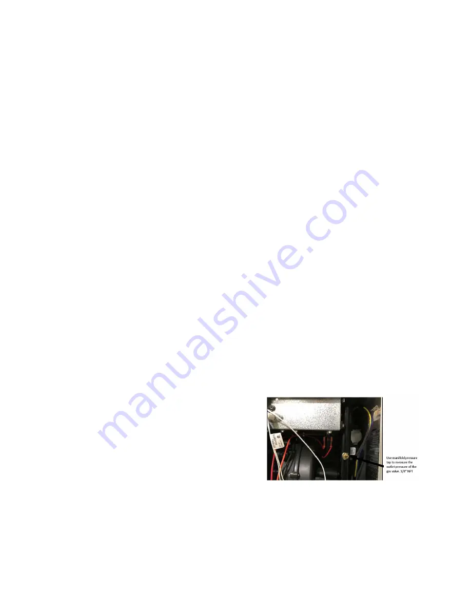
Figure 15 – Outlet pressure port
Gas outlet pressure should be set according to table 4.
A calibrated pressure gauge is required for gas pressure
measurements. Follow those steps to properly adjust the
servo gas valve :
1. Remove the square outlet pressure tap on the
manifold. Refer to figure 15.
2. Connect hose from a gauge to the pressure tap
(1/8" NPT).
14
Summary of Contents for CC15-M-V
Page 18: ...Figure 17 Wiring Diagram 18...
Page 23: ...Figure 25 Direct vent clearance 23...
Page 24: ...Figure 26 Other than Direct vent clearance 24...
Page 34: ...12 PART LIST Figure 27 Exploded view...
Page 35: ...Figure 28 Exploded view continued...
Page 36: ...Table 19 Part list Chinook Compact...
Page 37: ...Table 20 Part list continued...
Page 38: ...13 NOTES 38...
Page 39: ...39...
Page 40: ...40...


