6. Deburr the inside and outside of the pipe.
7. Chamfer the outside edge of pipe for better
distribution of primer and cement.
8. Clean and dry all surfaces to be joined.
9. Check dry fit of the pipe and mark insertion depth
on the pipe.
10. After the pipes have been cut and preassembled,
apply a generous layer of cement primer to the pipe
fitting socket and end of the pipe to insertion mark.
Quickly apply approved cement to end of the pipe
and fitting socket (over primer). Apply cement in a
light, uniform coat on the inside of socket to prevent
build-up of excess cement. Apply second coat.
11. While cement is still wet, twist pipe into the socket
with 1/4” turn. Be sure the pipe is fully inserted into
the fitting socket.
12. Wipe excess cement from the joint. A continuous
bead of cement will be visible around perimeter of
a properly made joint.
13. Handle pipe joints carefully until cement sets.
14. Horizontal portions of the venting system shall be
supported to prevent sagging. Support any piping
at a minimum of every 5 ft. using perforated metal
hanging strap or commercially available hangars
designed to support plastic pipe.
15. Prevent condensate from accumulating in the pipes
by sloping the combustion air piping and vent piping
downward toward furnace a minimum of 1/4” per
linear ft. with no sags between hangers.
16. Complete the vent installation by installing the
required termination.
allowed termination.
17. Use appropriate methods to seal the openings
where combustion air pipe and vent pipe pass
through roof or sidewall.
8.8
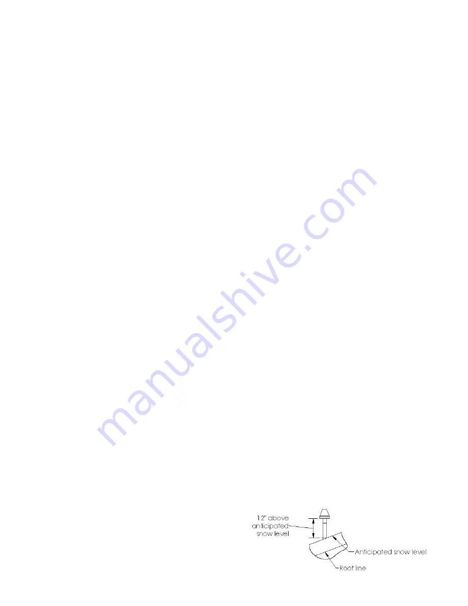
COMBUSTION AIR
Use a 90° elbow or two medium-radius sweep elbows to
keep the inlet downward and prevent the entry of rain.
The inlet opening of the combustion air termination must
be a minimum of 12” above the anticipated level of snow
accumulation.
Horizontal combustion air pipe should have a drain
tee assembly and trap installed in the as close to
the furnace as possible.
This is to drain any water or
condensate that may enter the furnace vestibule area.
8.9
VENT TERMINATION
All clearance specified in this manual are in accordance
with the current CSA B149.1, Natural and Propane
Installation Code and the current ANSI Z223.1/NFPA 54,
National Fuel Gas Code. For clearance not specified
in these codes, clearance should be in accordance with
local installation codes and the requirements of the gas
supplier and the instructions in this manual.
A vent for this appliance shall not terminate:
-over public walkways;
-near soffit vents or crawl space vents or other areas
where condensate or vapor could create a nuisance or
hazard;
-near regulators, relief valves, or other equipment where
condensate or vapor could be detrimental to their
operation;
See figures 25 and 26 for venting clearance.
8.9.1
Concentric vent
Concentric vent can cause ice build up at the termination
and cause the furnace to shut off. Especially this high
efficiency furnaces having an input below 15,000 BTU/hr.
In these installations, flue gases are not expelled at a
velocity to prevent ice formation and residual energy in
the flue is not high enough to prevent ice formation. If
a concentric vent is to be use with these low input, intall
a 1.5" diameter pipe within the 2" diameter pipe
in the
concentric
. Vent before the concentric shall remain 2"
diameter. This will enhance flue gas speed at the end of
the pipe and will reduce the risk of ice build up.
It might be necessary to add a heat strip
within
the
termination.
For multiple concentric installation, spacing of minimum
12" between each concentric is required.
Figures 18
and 19 show the required clearance for concentric
installation.
For installation through the roof or side wall, cut one 4”
(102 mm) diameter hole for 2” (51 mm) kit, or one 5”
(127 mm) diameter hole for 3” (76 mm) kit in the desired
location. Loosely assemble concentric vent/combustion
air termination components together following the kit
instructions.
Slide the assembled kit with rain shield
REMOVED through the hole in the wall or roof flashing.
NOTE
: Do not allow insulation or other materials to
accumulate inside the pipe assembly when installing it
through the hole. Disassemble loose pipe fittings. Clean
and cement using the same procedures as used for
system piping.
Figure 18 – Roof concentric termination
21
Summary of Contents for CC15-M-V
Page 18: ...Figure 17 Wiring Diagram 18...
Page 23: ...Figure 25 Direct vent clearance 23...
Page 24: ...Figure 26 Other than Direct vent clearance 24...
Page 34: ...12 PART LIST Figure 27 Exploded view...
Page 35: ...Figure 28 Exploded view continued...
Page 36: ...Table 19 Part list Chinook Compact...
Page 37: ...Table 20 Part list continued...
Page 38: ...13 NOTES 38...
Page 39: ...39...
Page 40: ...40...


