9
deliver a temperature rise within the range specified on the
rating plate, between the return and supply pressure at the
external duct static pressure noted on the rating label.
Adjust the fan speed ACCORDING TO THE OIL INPUT
SELECTED, so that the temperature rise is within the range
specified on the rating plate (see Table 2). Consult the
wiring diagram for speed changes on the direct drive motor.
In the oil mode, the blower start / stop is controlled by a
helical bi-metal Fan-Limit Control, which is adjusted to start
at 110°F and stop at 90°F. These are factory set li mits and
must not be changed or tampered with.
3.2.5
Limit Control check
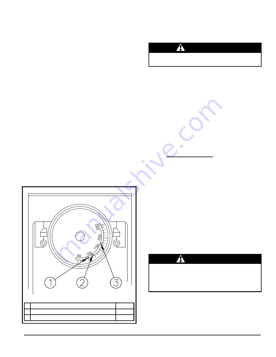
The Limit Control is factory adjusted according to Figure 1.
After the furnace has been in operation for at least 15
minutes, restrict the return air supply by blocking the filters or
closing the return registers and allow the furnace to shut
down on high limit. The burner will shut OFF and the main
blower should continue to run.
Remove the restriction and the burner should come back on
in a few minutes.
Constant Blower Switch
This furnace is equipped with a constant low speed blower
option. Whenever the room thermostat is not calling for
heating or cooling, the blower will run on low speed in order
to provide air circulation. If this constant blower option is not
desired, the rocker switch on the side of the control box can
be used to turn off this feature.
Figure 1 : Limit Control adjustment
DNS-0355 Rev A
1 Limit “FAN OFF”
90°F
2 Limit “FAN ON”
110°F
3 Limit “HI”
190°F
3.2.6
Limit Control adjustment
Changing the Low Limit "FAN ON" and limit "HI" on the Fan
limit control can cause malfunction of the furnace and cause
premature wear of the heat exchanger.
CAUTION
Modification of the factory set limits will void the
warranty.
3.2.7
BVSO performance test
The purpose of the following test is to check that the
electrical outlet on the furnace, designated to the BVSO, is
functional.
1. Start up the burner;
2. Remove the three-pole plug from the BVSO outlet on
the furnace;
3. The burner must shut-off immediately, while the blower
continues to run to the end of the cool-down cycle.
If the test is not in line with the above, call a QUALIFIED
SERVICE TECHNICIAN.
4.0 MAINTENANCE
This furnace should never be operated without an air filter.
Disposable filters should be replaced at least once a year. If
equipped to provide cooling, filters should be replaced a
minimum of twice a year.
In order to avoid injuries, be sure to cut the power to the unit
before commencing maintenance work.
For optimum performance, the oil burner nozzle should be
replaced at least once a year. Contact an authorized service
technician if you are unsure of this procedure.
The procedure for the installation and/or replacement of a
nozzle is outlined in the oil burner instruction manual that is
supplied with the furnace.
After replacing the nozzle, the burner should be adjusted in
accordance with the “COMBUSTION CHECK” section of this
manual.
WARNING
Be sure to turn all power “OFF” upstream from the unit
when servicing the furnace, unless power is required for
specific operations. Failure to comply with this
CAUTION can result in bodily harm and/or cause a fire
hazard.
4.1
HEAT EXCHANGER CLEANING
Ordinarily, it is not necessary to clean the heat exchanger or
flue pipe every year, but it is advisable to have a qualified
service technician check the unit before each heating
season to determine whether cleaning or replacement of
parts is required.
Summary of Contents for LOW-BOY AME15-79
Page 16: ...16 Figure 5 D montage du tiroir d l ment...
Page 17: ...17 Figure 6 Diagramme lectrique...
Page 18: ...18 Figure 7 Liste de pi ces B50047 Rev A...
Page 35: ...15 Figure 5 Element drawer removal...
Page 36: ...16 Figure 6 Electrical Diagram...
Page 37: ...17 Figure 7 Parts List B50047 Rev A...
Page 40: ...20...


