15
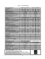
Table 6 - Technical Specifications
154 Series, m ulti-position m odels
Firing rate (USGPH)*
0,90
1,10
0,90
1,10
Input (BTU/h)*
126 000
154 000
126 000
154 000
Maximum Heating capacity, (BTU/h)*
107 000
129 000
107 000
129 000
Heating temperature rise (Degr. F)*
Flue draft w ith chimney (inch of w .c.)
Overfire pressure w ith chimney (inch of w .c.)
Flue pressure w ith direct vent (inch of w .c. - no w ind)
Overfire pressure w ith direct vent (inch of w .c. - no w ind)
BECKETT BURNER; MODEL NX (Chim ney or DV)
Burner tube insertion length (inches)
Head type
Nozzle (Delavan)
0.75 - 60B
0.90 - 60B
0.75 - 60B
0.90 - 60B
Minimum and Maximum pump pressure (PSIG)*
145
150
145
150
Head/Air setting
3,5
4
3,5
4
AFUE % (From CSA B212 standard and Canadian regulation)**
‡ 87,0%
‡ 85.7%
‡ 87,0%
‡ 85.7%
AFUE % (From ASHRAE 103 standard and US regulation)**
‡ 86.6%
‡ 85,2%
‡ 86.6%
‡ 85,2%
RIELLO BURNER; MODEL 40-F5 (Chim ney)
Burner tube insertion length (inches)
Nozzle (Delavan)
0.75 - 70A
0.90 - 70A
0.75 - 70A
0.90 - 70A
Minimum and Maximum pump pressure (PSIG)*
145
150
145
150
Combustion air adjustment (turbulator/damper)
1.5 / 2.25
2.5 / 2.75
1.5 / 2.25
2.5 / 2.75
AFUE % (From CSA B212 standard and Canadian regulation)**
‡ 86.7%
‡ 85.3%
‡ 86.7%
‡ 85.3%
AFUE % (From ASHRAE 103 standard and US regulation)**
‡ 86.3%
‡ 85,0%
‡ 86.3%
‡ 85,0%
RIELLO BURNER; MODEL 40-BF5 (Direct vent DV)
Burner tube insertion length (inches)
Nozzle (Delavan)
0.75 - 70A
0.90 - 70A
0.75 - 70A
0.90 - 70A
Minimum and Maximum pump pressure (PSIG)*
145
150
145
150
Combustion air adjustment (turbulator/damper)
1.0 / 3.75
3.0 / 4.25
1.0 / 3.75
3.0 / 4.25
AFUE % (From CSA B212 standard and Canadian regulation)**
‡ 86.7%
‡ 85.3%
‡ 86.7%
‡ 85.3%
AFUE % (From ASHRAE 103 standard and US regulation)**
‡ 86.3%
‡ 85,0%
‡ 86.3%
‡ 85,0%
Volts - Hertz - Phase
Rated current (Amps)
Minimum ampacity for w ire sizing (Amps)
Max. f use size (Amps)
Control transformer (VA)
External control pow er available Heating (VA)
Cooling (VA)
Heating blow er speed at 0.25" W.C. SP
MED-LOW
MED-HIGH
Heating blow er speed at 0.50" W.C. SP
MED-LOW
MED-HIGH
Motor (HP) / number of speeds
Blow er size (diam. x w idth)
Overall dimensions (w idth x depth x height)
Supply air opening (w idth x depth)
Return air opening (w idth x depth)
Filter size
Shipping w eight Lbs/Kg
Air conditioning, maximum output (tons) at 0.5" W.C. SP
5,0
5,0
24'' x 24'' x 1"
24'' x 24'' x 1"
200 / 90
200 / 90
20'' x 22''
20'' x 22''
23'' x 23''
23'' x 23''
12'' x 10'' (tight housing)
12'' x 10'' (tight housing)
GENERAL INFORMATION
25'' x 28 1/2'' x 48''
25'' x 28 1/2'' x 48''
BLOWER DATA
See the ECM air flow table
1.0 HP / 4 speeds
1.0 HP / ECM (w ith inductor)
40
40
30
30
20
20
40
40
16,9
15,7
19,5
18,1
2 3/4''
2 3/4''
ELECTRICAL SYSTEM
115 - 60 - 1
115 - 60 - 1
2 3/4''
2 3/4''
BF5
BF5
6 Slots - LC head
6 Slots - LC head
F5 WITH ELECTRIC AIR DAMPER
F5 WITH ELECTRIC AIR DAMPER
NX50LC
NX50LC
1 3/4''
1 3/4''
+0.05 to +0.16
+0.05 to +0.16
+0.06 to +0.22
+0.06 to +0.22
-0.06 to -0.035
-0.06 to -0.035
-0.035 to +0.045
-0.035 to +0.045
UNITS WITH 1.0 HP 4-SP. MOTOR
UNITS WITH 1.0 HP ECM MOTOR
RATING AND PERFORMANCE
55 - 75 Degr. F
60 - 72 Degr. F
* INPUT & OUTPUT ADJUSTMENT:
‡ =
- Pump pressure can be adjusted to maintain proper firing rate.
- Increase pump pressure if flue gases temperature is under 400˚F
- Adjust the total flue gas temperature between 400˚ and 575˚F (330˚ and 505˚ F net approx.)
- Adjust fan speed for air temperature rise of 55˚ to 85˚F.
** AFUE value established after minimum 20 hours of operation.
Summary of Contents for OMF154L20A
Page 18: ...18 Figure 9 Furnace Dimensions...
Page 19: ...19 Figure 10 Wiring diagram 4 speed motor PSC...
Page 20: ...20 Figure 11 Wiring diagram variable speed motor ECM...
Page 21: ...21 Figure 12 Parts list with 4 speed motor PSC B500111A...
Page 23: ...23 Figure 13 Parts list with variable speed motor ECM B50112A...


