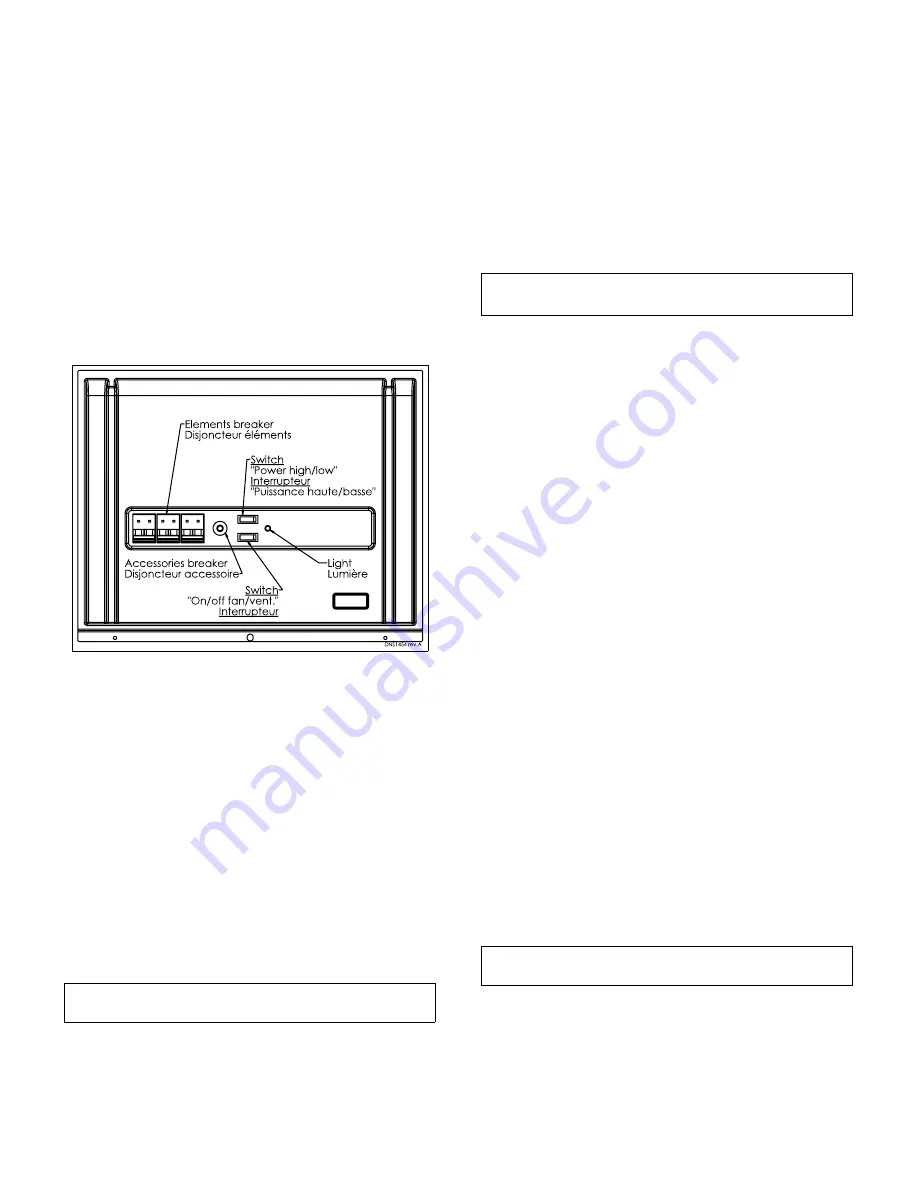
“HI” position during the winter months to ensure ad-
equate heating.
Also, this switch must remain in the “HI” position when a
2-stage or outdoor thermostat is used to control the elec-
tric elements of the second stage. Refer to the diagram in
Section 2.5. The “ON/OFF VENT/FAN” switch engages
the blower in the continuous low speed mode. This will
filter the air and provide for better air distribution in the
building.
The 15 A circuit breaker is there to protect the motor and
the control circuit conductors. If the unit does not func-
tion, press the circuit breaker button to see if it may have
disengaged due to a power surge. If the breaker has to
be pressed again, the unit must be checked by a qualified
service technician.
Figure 14: Advantage furnace controls
3.3
OPERATING SEQUENCE
This unit is designed to provide the required airflow in
order to match with any of four (4) different electronic
heat capacity, air conditioner or heat pump outdoor unit
sizes (see Tables 3 and 4 for CFM values).
Also, the blower motor is a true variable speed motor
designed to deliver constant CFM. Constant CFM is valid
for systems with total external static pressure between
0.1 and 0.8 inches water column.
Refer also to Table 1 for sequence of operation summary,
depending on thermostat inputs and types.
3.3.1
Continuous fan
a. Thermostat closes circuit R to G.
b. Blower runs at continuous fan airflow.
3.3.2
Cooling mode - single stage
NOTE
: For single stage systems, do not use the Y1 ter-
minal.
a. If indoor temperature is above temperature set
point and humidity is below humidity set point, ther-
mostat closes circuits R to G, R to Y/Y2 and R to
O.
b. Furnace delivers single stage cooling airflow.
3.3.3
Cooling mode - two stage
•
First stage (low) cooling
: Thermostat closes cir-
cuits R to G, R to O, and R to Y1.
Furnace delivers low stage cooling airflow.
•
Second stage (high) cooling
: Thermostat closes
circuits R to G, R to O, R to Y1 and R to Y/Y2.
Furnace delivers high stage cooling airflow.
3.3.4
Cooling mode – dehumidification
NOTE:
Remove jumper « J1 » on board to activate this
function. (Refer to Figure 10 and Figure 16)
a. If indoor temperature is above temperature set
point and humidity is above humidity set point, ther-
mostat closes circuits R to G, R to Y/Y2 and R to O
and humidistat opens circuit R to DH.
b. The furnace delivers airflow which is approximately
80% of the nominal cooling airflow to increase the
latent capacity of the system.
3.3.5
Electric heating mode - modulating
thermostat
The thermostat sends a heating demand in the form of a
pulse width modulated wave that varies between 5 and
100%. The heating unit will apply this power ratio to the
maximum available power. The electrical elements will
modulate to the required power and the fan will adjust
itself automatically in order to reach the required temper-
ature rise.
3.3.6
Electric heating mode -
Communicating thermostat
The thermostst sends a heating demand from 5 to 100%
using a communicating protocol. The heating unit will ap-
ply this power ratio to the maximum available power. The
electrical elements will modulate to the required power
and the fan will adjust itself automatically in order to reach
the required temperature rise.
3.3.7
Heat pump heating mode –
Modlating thermostat outdoor unit
single stage
NOTE:
For single stage systems, do not use the Y1
terminal.
a. Thermostat closes circuits R to G and R to Y/Y2.
b. Furnace delivers selected heat pump heating air-
flow.
9


