background image

either suspended or on a combustible floor with a choice
of right or left discharge, the clearances from combustible
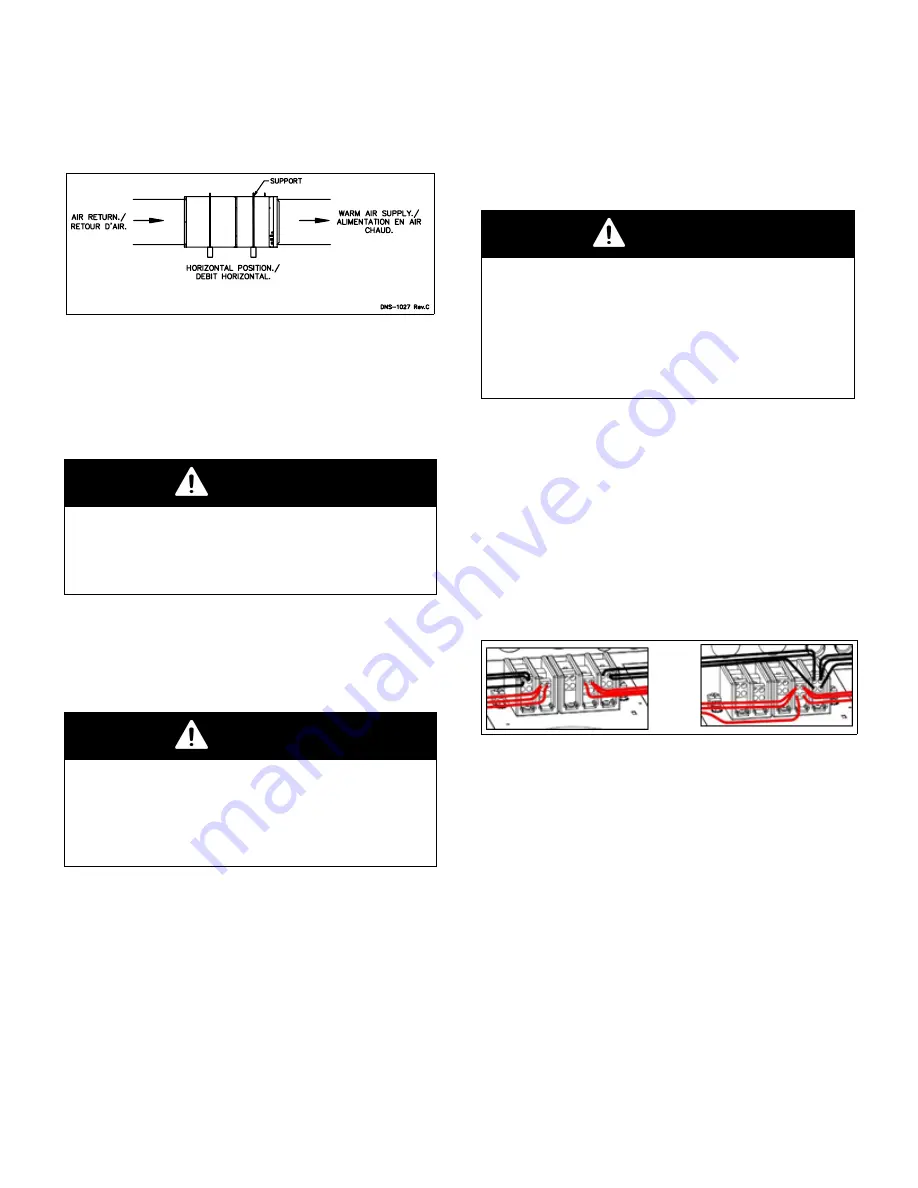
material must be adhered to. Refer to Figure 3 for addi-
tional details.

Figure 3: Horizontal Configuration

2.3.4

Suspended installation

The furnace can be hanged to the ceiling in either up-
flow, downflow or horizontal. Make sure to mount it ap-
propriately and to respect the clearances to combustible
material.

WARNING

The furnace must be properly secured especially
when installed above living space.
Failure to follow this rule can result in death, bod-
ily injury and/or property damage.

2.4

ELECTRICAL SYSTEM

The S

UPREME

furnace is completely pre-wired and all

field wiring must be connected to the terminal blocks on
the unit. It requires 2 service wires of 120/240 - 208 volts.

WARNING

R

ISK OF FIRE

The conductor sizing must conform to the last edi-
tion of the local or national codes.
Failure to follow this rule can result in death, bod-
ily injury and/or property damage.

Power supply to the unit can be done using cop-

per or aluminum wires. The wire size must be decided in
accordance to unit power consumption, the over current
protection type and capacity, the wire type and length,
and the environment where the unit is installed. If an alu-
minum wire is used, other precautions must be taken to
insure the conformity of the installation. In all cases, all
the factors affecting the wire gauge must be considered
and the installation codes followed.
The exterior of the unit must have an uninterrupted
ground to minimize the risk of bodily harm. A ground
terminal is supplied with the control box for that purpose.
A connector is supplied on the ground terminal to ground
an added accessory.

In the event that wires inside the unit require replace-
ment, these must be copper wires only with same tem-
perature rating and sizes as originals.

2.4.1

Conversion from two wires to one
wire supply for models 25kW and
more

WARNING

R

ISK OF FIRE

When using one terminal block on models of 25kW
and higher, the installation must be performed
with copper wire ONLY in order to comply with the
Canadian electrical code. The usage of an alu-
minum or copper wire is acceptable on models
25kW and lower.

Move all wires from the two pole terminal to the

three pole terminal following the corresponding colors as
shown in Figure 4.
The breaker and the supply conductors must be sized by
adding the ampacities of the two terminals indicated on
the nameplate. Refer to electrical diagram Figure 16.

Figure 4: Conversion from two to one supply wires

2.5

INSTALLATION OF THE
THERMOSTAT

A thermostat must be installed to control the temperature
of the area to be heated. Follow the instructions supplied
with the thermostat. Some thermostats need to connect
the C terminal on the furnace and thermostat. Install the
thermostat on an interior wall in a location where it will
not be subject to direct sunlight, lamps, air diffusers, fire-
places, etc. Seal openings in walls to avoid air currents
that may influence the operation of the thermostat. Also
refer to the wiring diagrams provided with the heating/air
conditioning unit. The connections must be made as in-
dicated on Figure 5 to Figure 9. Refer to the electrical
diagram (Figure 16).

4

Summary of Contents for SUPREME SUP A240V12 Series

Page 1: ...its controls Call a qualified service technician USE THE INFORMATION IN THIS MANUAL FOR THE IN STALLATION AND SERVICING OF THE FURNACE AND KEEP THE DOCUMENT NEAR THE UNIT FOR FUTURE REFERENCE HOMEOWN...

Page 2: ...mostat 9 3 3 6 Electric heating mode Communicating thermostat 9 3 3 7 Heat pump heating mode Modlating thermostat outdoor unit single stage 9 3 3 8 Heat pump heating mode Modulating thermostat outdoor...

Page 3: ...alified service technician immedi ately to assess the damage and to replace all criti cal parts that were in contact with water c Do not store gasoline or any other flammable sub stances such as paper...

Page 4: ...ample it is recommended to install the unit on a cement base 2 5 cm to 5 0 cm 1 to 2 thick In addition the heater should also be located close to the center of the air distribution system 2 2 CLEARANC...

Page 5: ...pted ground to minimize the risk of bodily harm A ground terminal is supplied with the control box for that purpose A connector is supplied on the ground terminal to ground an added accessory In the e...

Page 6: ...mode is comfort able and economical Generally speaking on a single stage thermostat a reading of the current must be taken with an ammeter as follows 1 Move the anticipator to its highest setting rend...

Page 7: ...d to operate prop erly with system components with which it is installed To successfully configure a system see information printed on circuit board label located next to select pins move the 6 select...

Page 8: ...t up cool down in conjunction with the airflow 3 0 0 No delay option Used for servicing unit or when a thermostat is utilized to perform delay func tions 4 ENH enhanced selection provides a 30 second...

Page 9: ...control will detect the humidistat contact opening on increasing humidity and reduce its airflow to approximately 80 of nominal cooling mode airflow This reduction will increase the system latent cap...

Page 10: ...o Y Y2 and R to O b Furnace delivers single stage cooling airflow 3 3 3 Cooling mode two stage First stage low cooling Thermostat closes cir cuits R to G R to O and R to Y1 Furnace delivers low stage...

Page 11: ...ir temperature from the supply air tempera ture If the temperature rise exceeds the temperature spec ified in Table 2 by 5 F 2 8 C move the AC HP CFM ADJUST black wire to high HI position If the exces...

Page 12: ...nt changes Dirty filters have an adverse ef fect on the performance of the central heating system 4 2 MOTOR LUBRICATION Do not lubricate the blower motor since it is permanently lubricated 5 FURNACE I...

Page 13: ...ected cooling delays Cooling 2 stages with Electric Heat Continous Fan G ON Fan ON at the selected continous fan CFM Fan switch ON OFF Fan OFF Thermostat calls for 1st stage Heat W1 ON Fan ON at 50 of...

Page 14: ...DH ON Compressor ON Fan ON after delays at 80 of the selected Cooling CFM OFF Compressor OFF Fan OFF after selected cooling delays Thermostat calls for 1st stage Heat Heat pump heating mode Y1 G ON Co...

Page 15: ...5 3 7 4 3 1 5 3 7 Electrical element 6 240V 208V Kw 4 3 1 5 3 7 Blower motor Consumption 240V 208V Amp Max 2 3 2 7 2 3 2 7 2 3 2 7 2 3 2 7 2 3 2 7 2 3 2 7 5 2 6 0 5 2 6 0 5 2 6 0 5 2 6 0 5 2 6 0 Heati...

Page 16: ...sides the back and below KOE Identical on the 2 sides Identique sur les 2 cot s KOE A 35mm 44mm 1 3 8 1 3 4 B 29mm 7 8 A B Identique sur les 2 cot s au dos et en dessous DNS1455 rev C 927mm 36 1 2 559...

Page 17: ...s 24VAC input to Y1 only Y Y2 not powered CONTINUOUS FAN CFM1 CFM1 CFM1 AC HP SIZE A C size CONTINUOUS FAN CONTINUOUS FAN CONTINUOUS FAN Selection TONS YELLOW wire position YELLOW wire position YELLOW...

Page 18: ...to Y1 only Y Y2 not powered CONTINUOUS FAN 24 VAC R input on G only CFM1 CFM1 CFM1 AC HP SIZE A C size CONTINUOUS FAN CONTINUOUS FAN CONTINUOUS FAN Selection TONS YELLOW wire position YELLOW wire pos...

Page 19: ...ON OFF DELAY Adjustment ON Delay OFF Delay WHITE wire position Time CFM Time 0 90 0 sec 100 90 sec 30 90 30 sec 100 90 sec 0 0 0 sec 0 sec ENH 30 sec 70 150 sec DELAY PROFILE FOR ELECTRIC HEATING MODE...

Page 20: ...Figure 16 Electrical diagram SUPREME Advantage ECM ELECTRICAL DIAGRAM DIAGRAMME LECTRIQUE ADVANTAGE AVANTAGE ECM 19...

Page 21: ...rev E 31 12 15 16 17 11 6 8 9 18 19 20 21 22 13 14 7 10 REV DESCRIPTION A C DATE PAR A Nouveau dessin 21963 2015 03 24 F H B Changement disjoncteur CQC 22327 2015 05 19 F H C Ajoute support de filtre...

Page 22: ...upreme 15kw 21 B04284 Electrical sequencer kit Supreme 10kw 22 B04350 02 Top door 23 B04349 Bottom door assembly 24 B04357 01 Blower assembly Supreme 10 25kw 1 2hp ECM 25 B04357 02 Blower assembly Sup...

Reviews: