Modular Multi-service Integrated Optical Transmission Multiplexer
User Manual
24
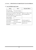
2. Failure with Electrical Interface (E1 or V.35)
Effect
Cause
Diagnostic Method
E1 or V.35
Interface Alarm
Failure with line,
or failure with
E1/V.35 interface
board, or optical
multiplexer
To be connected with self looping head,
and it indicates a failure with line if
connection with self-looping head is
normal, and it indicates a failure with
E1/V.35 interface board or optical
multiplexer if connection with
self-looping head is not normal.
3. Failure with Optical Interface
Effect
Cause
Diagnostic Method
Both ends receive
no-output alarm
If self loop for both ends is
normal and transmission
fiber is correctly connected,
while they still receive
no-output alarm, then it is a
failure with transmission
fiber.
Replace transmission
fiber or detect the failure
point with optical
time-domain
reflectometer, to remove
the failure with
transmission fiber.
One end is normal
while the other end
receives no-output
alarm
Self loop the two ends
separately, and if one end is
normal and the other
experiences alarm, then the
end with alarm for self loop
is the end with failure.
Please replace equipment
or measure optical power
or contact supplier for
recovery
4. Failure with Order Wire
Effect
Cause
Diagnostic Method
Noisy
Weak Optical Signal
Measure optical power.
Be Obstructed
Line Broken or Failure with
Order Wire
Replace telephone set or
recover order wire.


