User Manual
Modular Multi-service Integrated Optical Transmission Multiplexer
19
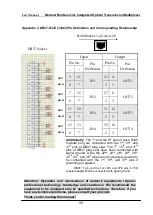
III) When 4×RS422/485 interface board is plugged in, the switch is
used for option of RS422/RS485.
1 (The 1
st
Interface)
2 (The 2
nd
Interface)
3 (The 3
rd
Interface)
4 (The 4
th
Interface)
ON
OFF
ON
OFF
ON
OFF
ON
OFF
RS485
RS422
RS485
RS422
RS485
RS422
RS485
RS422
IV) When other interface boards are plugged in, the 4-digit patch
switch would possibly be invisible.
§6.8 Power Supply Receptacle
T
T
h
h
e
e
M
M
o
o
d
d
u
u
l
l
a
a
r
r
I
I
n
n
t
t
e
e
g
g
r
r
a
a
t
t
e
e
d
d
O
O
p
p
t
t
i
i
c
c
a
a
l
l
M
M
u
u
l
l
t
t
i
i
p
p
l
l
e
e
x
x
e
e
r
r
is normally provided with
DC-48V power supply, with the dual power supply of DC-48V/AC220VAC
as optional.
When DC-48V power supply is used to supply power to the
equipment, input mode with positive and negative poles inversed is also
acceptable.
VII. Installation and Maintenance of Optical Multiplexer
(Taking DC-48V power supply for example)
§7.1 Equipment Package and Appearance Check
1) After equipment arrives, first check if its external packing is damaged
or not. Contact the After-Service Department of our Company at once
if there is any serious damage, for timely solutions.
2) After the equipment is unpacked, check it as per packing list. Please
contact the installers or the After-Service Department of our
Company directly, if any damage is found with exterior of the machine
frame, for timely replacement.
Ⅰ
Ⅱ
Ⅲ
Ⅳ
ON
O
FF
1
2
3
4
ON
O
FF
ON
O
FF
1
2
3
4
ON
O
FF
1
2
3
4


