User Manual
Modular Multi-service Integrated Optical Transmission Multiplexer
33
Input
Output
Pin No.
Pin
Definition
Pin No.
Pin
Definition
–
+
–
+
3
21
IN1
23
4
OUT1
6
7
2
3
7
25
IN2
27
8
OUT2
6
7
2
3
11
29
IN3
31 12
OUT3
6
7
2
3
15
33
IN4
35 16
OUT4
6
7
2
3
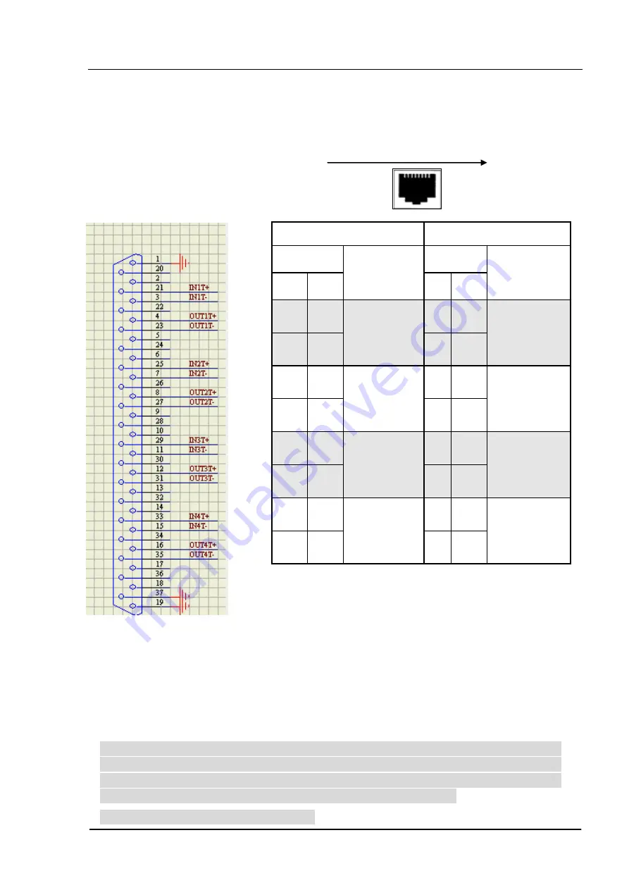
Additionally:
The 1
st
and the 8
th
pins of each RJ45
modular plug are connected with the 1
st
, 19
th
, and
37
th
pins of DB37 plug seat. The 1
st
, 19
th
, and 37
th
pins of DB37 plug seat have been connected with
signal ground, while the 22
nd
, 24
th
, 26
th
, 28
th
, 30
th
,
32
nd
, 34
th
, and 36
th
pins are not connected, and are to
be connected with the 1
st
, 19
th
, and 37
th
pins if
grounding is required.
DB37 “-” pin and the 1st, 19th, and 37th pins in 75Ω
coaxial adapter shall be connected with signal ground.
Appendix 2. DB37-RJ45 (120
Ω) Pin Definitions and Corresponding Relationship
RJ45 Socket: 1,2,3,4,5,6,7,8
DB37
RJ45-1
DB37 Socket
DB37
RJ45-2
DB37
RJ45-3
DB37
RJ45-4
Attention: Operation and maintenance of network equipments requires
professional technology, knowledge and experience. We recommend the
equipment to be managed only by qualified technicians. Therefore, if you
have any technical problems, please consult your provider.
Thank you for reading this manual !


