4.12.20
Instruction manual ROTARNOCK 100 V. 3.6
31
Deutschmann Automation GmbH & Co. KG
Configurations ROTARNOCK 100
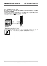
5.10.6 Graphical illustration of example 1
Picture 6:
Example, logic operation
5.10.7 Example 2
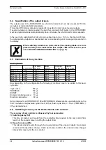
Following please find an example whose result causes output 8 to blink: (represented on operat-
ing panel TERM 24)
5.11 Count cam
The user has the possibility to have switched a certain output only on the revolution set by him-
self (1... 32). The count cam is realized through the logic function.
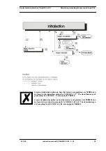
Following please find an example which shows the output 1 only switches every fifth 5 revolution:
A1 (output1)
=
N1 and M1
M1
=
N1 and M1 or M16
M14
= N1
M15
= N1
M16
=
S5 (5. revolution)
Summary of Contents for ROTARNOCK 100
Page 2: ...Manual Art No V3408E...
Page 4: ...Deutschmann Automation GmbH Co KG 4 Instruction manual ROTARNOCK 100 V 3 6 4 12 20...
Page 57: ......
Page 58: ......

