background image

4.12.20

Instruction manual ROTARNOCK 100   V. 3.6

35

Deutschmann Automation GmbH & Co. KG

Networking terminals with cam controls and PCs 

6.5  Connection examples

6.5.1 DICNET link LOCON-TERM

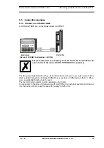
LOCON and TERM are connected as follows via DICNET

Picture 8:


DICNET link terminal - LOCON

The presented devices exemplary stand for Deutschmann terminals and 
cam controls of the series LOCON / ROTARNOCK respectively.

The two ground potentials do not have to be interconnected. However, you must ensure that the 
GND potential between the individual DICNET bus users does not differ by more than 7V. Other-
wise, equipotential bonding must be used.
The bus termination resistor must be activated on both units.
Consequently, in the case of simple wiring with a LOCON and an external operator control panel, 
it is the obvious choice to use the same 24V supply for both units.

Summary of Contents for ROTARNOCK 100

Page 1: ...Instruction manual Electronic cam control ROTARNOCK 100 Deutschmann Automation GmbH Co KG www deutschmann com wiki deutschmann de...

Page 2: ...Manual Art No V3408E...

Page 3: ...AUTOMATION reserves the right to carry out alterations to the described products in order to improve the reliability function or design thereof DEUTSCHMANN AUTOMATION only accepts liability to the ex...

Page 4: ...Deutschmann Automation GmbH Co KG 4 Instruction manual ROTARNOCK 100 V 3 6 4 12 20...

Page 5: ...NOCK 100 PN PROFINET 14 3 1 3 1 GSDML file PROFINET 14 3 1 3 2 Configuration via PROFINET interface 14 3 1 3 3 Programming via PROFINET 14 3 1 3 4 Operation via PROFINET interface 14 3 1 3 5 Example p...

Page 6: ...N 26 5 3 3 PNR_ENCODER_INVERT 26 5 3 4 PNR_LANGUAGE language selection 26 5 3 5 PNR_DEADTIME_TYP 26 5 4 Configuration parameters ROTARNOCK 100 26 5 4 1 Inputs and logic functions 26 5 5 Angle time cam...

Page 7: ...2 5 DICNET device number GNR 42 7 3 2 6 Zero offset 42 7 3 2 7 Scaling for speed display 42 8 Technical details 43 8 1 Technical data ROTARNOCK 100 43 8 2 ROTARNOCK 100 memory expansion 43 8 3 Specifi...

Page 8: ...l ROTARNOCK 100 V 3 6 4 12 20 10 Order Code 54 10 1 Cam control ROTARNOCK 100 54 10 1 1 Explanation of the order designation 54 10 2 Scope of delivery 54 10 2 1 Scope of delivery ROTARNOCK 100 54 11 S...

Page 9: ...seen from the adjacent pictogram You should always follow this information since otherwise this could result in malfunctions or operating errors 1 1 2 Concepts The expressions LOCON ROTARNOCK and TERM...

Page 10: ...ined as a cam Each switch represents one output Several circuits arranged in parallel produce the number of outputs Picture 1 Mechanical cam control This basic principle has been adopted from the mech...

Page 11: ...oducts of DEUTSCHMANN AUTOMATION 2 EMC Directives for products of DEUTSCHMANN AUTOMATION The installation of our products has to be carried out considering the relevant EMC directives as well as our i...

Page 12: ...LOC 32 soft ware These include Dead time compensation bit wise block wise block wise I O and bit wise I O The delivery status is bit wise dead time compensation Logic inputs only ROTARNOCK with bus sy...

Page 13: ...you have a current device V2 1 in want to replace an existing project you can change the Ident No to the old version Reset 3231h by entering STRG N and confirming the security query 3 1 2 6 PROFIBUS s...

Page 14: ...mmunication profile for Deutschmann Cam controls see corresponding manual V2064 carried out 3 1 3 3 Programming via PROFINET The cams and dead times are programmed via PROFINET in the data structure s...

Page 15: ...RS232 or RS485 option IF version IP65 Picture 3 Dimensional drawing ROTARNOCK RS232 or RS485 or PROFIBUS version IP54 Picture 4 Dimensional drawing ROTARNOCK with PROFIBUS or Fieldbus version IP65 x...

Page 16: ...mber in the DICNET and allows to acti vate an internal bus terminating resistor The device number is connected to the plug with a binary code where a connection to GND is made at those pins that are m...

Page 17: ...continuing bus 4 5 Pin assignment 16 pol round plug at ROTARNOCK PROFIBUS with IP65 Pin No Significance 1 DICNET No 1 2 DICNET No 2 3 DICNET No 4 4 DICNET No 8 5 GND 6 DICNET 7 R 8 DICNET 9 R Pin No...

Page 18: ...11 I O 11 output 11 or external PB ID selection 4 12 I O 12 output 12 or external PB ID selection 8 13 Tx 14 Rx 15 24 VDC 16 GND Pin No Name 1 TD RJ45 Pin 1 2 RD RJ45 Pin 3 3 TD RJ45 Pin 2 4 RD RJ45 P...

Page 19: ...ET ID is set through the DIP switch at the back of the unit The switch is accessible after removing the protecting cover screw top Please take the meaning from the below table 24 V DC Red yellow black...

Page 20: ...t circuit proof Total current of the output block maximum 1 A X X Output 9 12 Output block 2 Each output 24V 0 3A plus switching PNP short circuit proof Total current of the output block maximum 1 A X...

Page 21: ...m can be changed any time using the connector strip If pin PROG_START is permanently wired to 24V ROTARNOCK accepts the program applied externally each time the unit is powered up 4 11 Installation an...

Page 22: ...ng 24V i e an active output has a level equal to the supply voltage less 1V by comparison with GND An output which has been reset has high impedance The outputs are short circuit proof and may drive m...

Page 23: ...4 12 20 Instruction manual ROTARNOCK 100 V 3 6 23 Deutschmann Automation GmbH Co KG Pin assignment ROTARNOCK Please always follow the information in chapter RS485 link DICNET...

Page 24: ...ain menu the keys and are pressed for the same time period Thereupon the function LED shines and a 1 current parameter number appears on the display Now this number can be changed with and see paramet...

Page 25: ...rams PNR_NUMBER_AXIS 0x0027 39 Number of axes PNR_NUMBER_ANALOGOUTPUT 0x0028 40 Number of analog outputs PNR_NUMBER_COUNTERCAM 0x0029 41 Number of counter cams PNR_FIRST_OUTPUT_NR 0x002A 42 Counting s...

Page 26: ...uration parameters ROTARNOCK 100 The following performance characteristics can be configured at ROTRANOCK 100 5 4 1 Inputs and logic functions ROTARNOCK 100 is optionally available with 16 inputs thro...

Page 27: ...g can be configured for Singleturn applications It compares the encoder value read in each cycle with the value read in before and generates an Error 105 if a deviation greater than 7 increments has b...

Page 28: ...stable from 0 static to 255 equals 2 55 seconds By default the value is set to 50 whereby a toggle of 500 ms is achieved 5 9 Incremental output generation of A B track Via WINLOC32 two A B tracks can...

Page 29: ...egister Referring to bottle manufacturing the finished product has to be analyzed for various criterions Therefore the bottles are handed over to a rotary table For the examination they are placed in...

Page 30: ...Example 1 An example with 3 inputs and a switch off delay is given below The above example is displayed on an operating panel TERM 24 In this example the status of output 1 results as follows The pro...

Page 31: ...example whose result causes output 8 to blink represented on operat ing panel TERM 24 5 11 Count cam The user has the possibility to have switched a certain output only on the revolution set by him se...

Page 32: ...to the ROTARNOCK via the PC s serial port It is also possible to transfer existing programs from ROTARNOCK to the PC change these pro grams on the PC and then re load them back into the cam control T...

Page 33: ...e ground potentials as on the RS232 interface however you must ensure that the potential difference between the individual devices does not exceed 7V Consequently equipotential bonding is generally ca...

Page 34: ...tted with a line termination This avoids sig nal reflections on the line and ensures a defined open circuit potential if no user is transmitting state of rest between the telegrams so called idle stat...

Page 35: ...mann terminals and cam controls of the series LOCON ROTARNOCK respectively The two ground potentials do not have to be interconnected However you must ensure that the GND potential between the individ...

Page 36: ...LOCON and the external opera tor control panel is possible In this case the Tx LOCON line must be connected to the Rx TERM line of the operator control unit and vice versa as can be seen from the ill...

Page 37: ...3 DICNET link LOCON TERM PC A PC can be integrated in a DICNET bus system using a DICNET adapter The connection to the PC is made at a serial port COMx see the illustration below Picture 10 Link DICNE...

Page 38: ...Networking terminals with cam controls and PCs Deutschmann Automation GmbH Co KG 38 Instruction manual ROTARNOCK 100 V 3 6 4 12 20 6 6 Short instuction...

Page 39: ...the device is programmed via TERM 6 can be found in the instruction manual for LOCON 16 17 The described ways of proceeding for LOCON 16 17 also apply for TERM 6 A more detailed description on how the...

Page 40: ...ght Should errors occur during the self test these are displayed on the display if possible see chap ter Error messages 7 2 Commissioning of the cam control The commissioning procedure for the ROTARNO...

Page 41: ...e resolution of the internal encoder it is possible to program a virtual encoder resolution thus implementing an electronic transmission If for example an encoder with a real resolution of 360 increme...

Page 42: ...e ROTARNOCK logs on to the DICNET bus and with which for example it is addressed by WINLOC32 or communicates with TERM This value can be changed only with the config plug and not in the menu If you us...

Page 43: ...er Outputs To be programmed as desired short circuit proof plus switching 24 volt 0 7A For version with IP65 only 12 hard ware outputs Idle time compensation ITC Bitwise Blockwise separate I O input o...

Page 44: ...cle times have to be added to this basic cycle time Logic active 450 s PROFIBUS 150 s DICNET 40 s Encoder monitoring active 10 s Direction cams active 60 s So for instance for a ROTARNOCK 100 with PRO...

Page 45: ...still reliably detected and set by the cam control If the encoder speed Vencoder is exceeded n fold the resolution increases accordingly to n increments If you work with idle time compensation the er...

Page 46: ...s between accessing the circuit component and the mechanical reflex lies a constant time the idle time The compensation of this idle time depends on the speed of the cam control The following processe...

Page 47: ...ompensation With this method the actual idle time value is adapted for maximal 1 increment in every cycle of the cam control By that it is guaranteed that no cams are skipped over during the accelerat...

Page 48: ...ation is conducted and an error message is issued should a transmission error occur twice The maximum extent of the network may not exceed 500 m In order to avoid transmission errors it must be ensure...

Page 49: ...evice number is set in hexadecimal code on the config plug The following assignment applies Display Device number Binary coding 8 4 2 1 0 0 0 0 0 0 1 1 0 0 0 1 2 2 0 0 1 0 3 3 0 0 1 1 4 4 0 1 0 0 5 5...

Page 50: ...ing an idle time 27 Record number not available At S7 data block 30 No programming enable The program can be modified only if signal Prog Freigabe Program Enable is at 24V on the con nector or if para...

Page 51: ...on transmission 41 DICNET receive error Duplicate error on receive 42 DICNET ID error There is already a user with the same device num ber GNR in the network or the network line is faulty missing bus...

Page 52: ...he encoder line must be checked and exchanged if necessary If the error still persists the unit must be returned see chapter Returning a unit 101 Checksum error on the memory card or in EEPROM If a ch...

Page 53: ...cam control 221 Incorrect data record on transmission to cam control 222 Checksum error on reception from cam control 223 Checksum error on transmission to cam control 224 Unknown command on transmiss...

Page 54: ...ignation ROTARNOCK 100 is available in three different versions 1 ROTARNOCK 100 with RS232 interface 2 ROTARNOCK 100 with RS485 DICNET interface 3 ROTARNOCK 100 PB with PROFIBUS and RS232 interface 10...

Page 55: ...than 3 working days Technical Support hours are as follows Monday to Thursday from 8 am to midday and from 1 pm to 4 pm Friday from 8 am to midday CET Deutschmann Automation GmbH Co KG Carl Zeiss Str...

Page 56: ...on undergo a standard test You have to bear the costs for that test even though no defect was found 11 2 Internet The current software WINLOC32 is available for download from our Internet homepage www...

Page 57: ......

Page 58: ......

Reviews: