Hardware ports, switches and LEDs
Deutschmann Automation GmbH & Co. KG
22
UNIGATE Fieldbus Gateway CANopen® - ProfibusDP V. 2.3
26.8.11
5.4.6
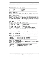
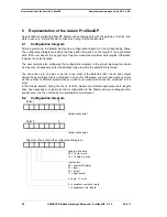
LEDs “Error No. / Select ID“
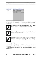
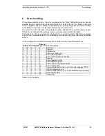
If these 4 LEDs flash and LED “State“ simultaneously lights red, the error number is displayed in
binary notation (conversion table, see Annex) in accordance with the table in Chapter "Error
handling". Otherwise, the number of the sent CAN-records is indicated with the LEDs 1 + 2, and
with the LEDs 3 + 4 the number of received CAN-records is indicated, also in binary notation.
5.5
Switches
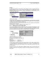
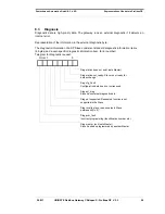
The gateway features 5 switches with the following functions:
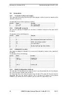
Rotary coding switch, Profibus High
ProfibusDP ID (High Byte)
Rotary coding switch, Profibus Low
ProfibusDP ID (Low Byte)
Slide switch “Termination“
Switchable ProfibusDP terminating resistor
DIP switch CANopen®
Node-ID and baud rate
Slide switch “Termination“
Switchable CANopen® terminating resistor
5.5.1
Rotary coding switch (Profibus ID)
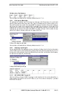
These two switches are used to set the Profibus ID (00..7D) of the gateway in hexadecimal nota-
tion. A conversion table from decimal to hexadecimal can be found in the Annex. This value is
read in only once when the gateway in activated and cannot be changed via the Profibus.
5.5.2
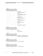
Slide switch Termination Profibus
If the gateway is operated as the first or last physical device in the ProfibusDP, there must be a
bus termination at this gateway. In order to do this, either a bus terminating resistor must be acti-
vated in the connector or the resistor (220
) integrated in the gateway must be activated. In
order to do this, slide the slide switch to position ON. In all other cases, the slide switch must
remain in position OFF. Please refer to the general Profibus literature for further information on
the subject of bus termination.
5.5.3
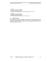
Dip-switch
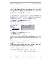
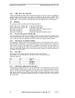
This switch is used to set the Node-ID and the baud rate of the CAN-bus.
With the bits 2 to 7 the Node-ID is set, with the bits 0 and 1 the baud rate is set.
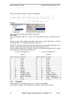
Setting the baud rate
Bit 0
Bit 1
Baud rate
0
0
1 MB
0
1
500 kBaud
1
0
250 kBaud
1
1
125 kBaud
:
5.5.4
Slide switch (CANopen® Termination)
If the gateway is operated as the first or last physical device in the CANopen® bus, there must be
a bus termination at this gateway. In order to do this, either a bus terminating resistor in the con-
nector or the resistor (120
) integrated in the gateway must be activated. In order to do this,
slide the slide switch to position ON. In all other cases, the slide switch must remain in position
OFF. Please refer to the general CANopen® literature for further information on the subject of
bus terminations.

