background image

Technical data

Deutschmann Automation GmbH & Co. KG

55

UNIGATE

®

 fieldbus gateway UNIGATE

®

 EL - DeviceNet

  V. 1.0

22.6.17

16.1.1 Interface data 

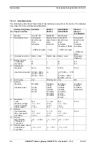
The table below lists the technical data of the interfaces and ports on the device. The data has 
been taken from the corresponding Standards.

Interface designation DeviceNet

RS232-C

RS485/RS422

Ethernet

No. Physical interface

RS232-C

RS485/RS422

Ethernet 
10/100BASE-T

1

Standard

CiA

®

 DS 102

DIN 66020

EIA Standard

2

Transmission mode

Symmetrical
asynchronous
serial
half-duplex



Difference signal

Asymmetrical
asynchronous
serial
full duplex



Level

Symmetrical
asynchronous
serial 
half-duplex
full duplex at RS422



Difference signal

Symmetrical
asynchronous
serial
full duplex
half-duplex



Difference 

signal

3

Transmission method

Master / slave

Master / slave Master / slave

Multimaster
CSMA/CD

4

Number of users:

- Transmitters 
- Receivers

32
32

1
1

32
32

512
512

5

Cable length:

- Maximum 
                           
- Baud rate-dependent

500 m
     
125 kB 

 500 m

250 kB 

 250 m

500 kB 

 100 m

15 m

no

1200 m

93.75 kBd 

 1200 

m
312, kBd 

 500 m

625 kBd 

 250 m

100 m

6

Bus topology 

Line

Point-to-point

Line

Star

7

Data rate:

- Maximum 

- Standard values

500 kBit/s

125 kB
250 kB
500 kB
    

120 kBit/s
2.4 k/B
4.8 k/B
9.6 kBit/s
19.2 kBit/s
38.4 kBit/s
57.6 kBit/s

625 kBaud
2.4 kBit/s
4.8 kBit/s
9.6 kBit/s
19.2 kBit/s
57.6 kB
312.5 kB
625 kB

100 Mbit/s
10 Mbit/s
100 Mbit/s
(autodetect)

8

Transmitter:

- Load 
- Maximum voltage 
- Signal, unloaded 
- Signal, loaded 

54 

- 7 V ... 12 V

 5 V

 1.5 V

3 ... 7 k

 25 V

 15 V

 5 V

54 

- 7 V ... 12 V

 5 V

 1.5 V

100 

9

Receiver:

- Input resistance 
- Max. input signal
- Sensitivity 

12 

- 7 V ... 12 V

 0.2 V

3 ... 7 

 15 V

 3 V

12 

- 7 V ... 12 V

 0.2 V

100 

10 Transmit 

range (SPACE): 
- Voltage level 
- Logic level

- 0.5 ... + 0.05 V
0

+ 3 ... + 15 V
0

- 0.2 ... + 0.2 V
0

11

Transmit pause  

(MARK):

- Voltage level 
- Logic level 

+ 1.5 ... +3 V
1

- 3 ... –15 V
1

+ 1.5 ... +5 V
1

Summary of Contents for UNIGATE EL-DeviceNet

Page 1: ...Instruction Manual Universal Fieldbus Gateway UNIGATE EL DeviceNetTM Deutschmann Automation GmbH Co KG www deutschmann com wiki deutschmann de ...

Page 2: ...Manual Art No V4149E ...

Page 3: ......

Page 4: ... 15 5 RS interface 16 5 1 RS interfaces at the UNIGATE EL 16 5 2 Buffer sizes at the UNIGATE EL 16 5 3 Framing Check 16 6 The Debug interface 17 6 1 Overview of the Debug interface 17 6 2 Starting in the Debug mode 17 6 3 Communication parameter for the Debug interface 17 6 4 Possibilities with the Debug interface 17 6 5 Commands of the Debug interface 17 7 Mode of operation of the system 19 7 1 G...

Page 5: ...rror handling at UNIGATE EL 28 10 1 1 Error on the extension 30 11 Installation guidelines 31 11 1 Installation of the module 31 11 1 1 Mounting 31 11 1 2 Removal 31 11 2 Wiring 31 11 2 1 Connection systems 31 11 2 2 DeviceNet communication interface 32 11 2 3 Line routing shield and measures to combat interference voltage 32 11 2 4 General information on line routing 32 12 Firmware Update 34 13 D...

Page 6: ...k Start 52 15 5 Trigger Byte 53 15 6 Length Byte 53 15 7 Swap word 53 16 Technical data 54 16 1 Device data 54 16 1 1 Interface data 55 17 Commissioning guide 56 17 1 Note 56 17 2 Components 56 17 3 Installation 56 17 4 Dimensional drawing UNIGATE EL DeviceNet 56 17 5 Commissioning 56 17 6 Setting the DeviceNet address and baud rate 57 17 7 DeviceNet connection 57 17 8 Ethernet connection 57 17 9 ...

Page 7: ...Deutschmann Automation GmbH Co KG 7 UNIGATE fieldbus gateway UNIGATE EL DeviceNet V 1 0 22 6 17 ...

Page 8: ... in the publication is however reviewed regularly Necessary amendments are incorporated in the following editions We would be pleased to receive any improvement proposals which you may have Copyright Copyright C Deutschmann Automation GmbH Co KG 1997 2016 All rights reserved This document may not be passed on nor duplicated nor may its contents be used or disclosed unless expressly permitted Viola...

Page 9: ...irements if you 1 comply with the installation guidelines described in the User Manual when installing and oper ating the module 2 also follow the rules below on installation of the equipment and on working on switch cabinets 1 4 Installation of the unit Modules must be installed in electrical equipment rooms areas or in enclosed housings e g switch boxes made of metal or plastic Moreover you must...

Page 10: ...tive Consequently the module does not have a Declaration of Conformity in relation to the EU Machinery Directive 2 2 EU Machinery Directive The EU Machinery Directive stipulates the requirements applicable to a machine The term machine is taken to mean a totality of connected parts or fixtures see also EN 292 1 Para graph 3 1 The module is a part of the electrical equipment of the machine and must...

Page 11: ...rates as DeviceNet Group 2 Only Slave It can be operated by any standard compliant Master The module EL DeviceNet essentially consists of the following hardware components Electrically isolated interface to DeviceNet CAN controller SJA 1000 Microprocessor 89C51RE2 RAM and EPROM Serial interface RS232 RS485 and RS422 to the device connected externally 10 100 Base T Ethernet LAN RJ 45 connector Conc...

Page 12: ...22 6 17 UNIGATE fieldbus gateway UNIGATE EL DeviceNet V 1 0 12 Deutschmann Automation GmbH Co KG Introduction 3 1 UNIGATE EL software flow chart ...

Page 13: ... Co KG 13 UNIGATE fieldbus gateway UNIGATE EL DeviceNet V 1 0 22 6 17 3 2 UNIGATE block diagram The following picture shows a typical UNIGATE module design 3 3 UNIGATE application diagram The following graph shows a typical connection scheme ...

Page 14: ...G S Version V1 6 0 Date 30 09 2016 SN 47110001 Ext Board EL IO DICNET 193 V1 51 c dA 47110211 FE IP 0 0 0 0 MAC 00 14 11 15 1A 53 Data Flash 1MB In the configuration mode the Gateway always operates with the settings 9600 Bauds no Parity 8 databits and 1 stopbit the RS State LED will always be flashing red the Error No Select ID LEDs are of no account for the user All software revisions contain th...

Page 15: ...g red the Error No Select ID LEDs will be displaying the value in a binary way that is issued that moment Additionally each character that is received at one of the interfaces will also be output at the same interface as a local echo On the fieldbus side only the first byte will be used for the local echo that means on receiving as well as on transmitting only the first byte of the bus data is loo...

Page 16: ...at is capable for Script For it please check in the PROTOCOL DEVELOPER under Device Control Hardware 5 3 Framing Check The length of the stop bit received by the Gateway is checked through the function Framing Check Here the stop bit generated by the Gateway is always long enough so that connected participants can evaluate the stop bit Please be aware that the function Framing Check becomes effect...

Page 17: ...rface With it a step by step processing of a Script monitoring jumps and decisions and looking at memory areas is possible Moreover breakpoints can be set It basically possesses all characteristics a software development tool is typically supposed to have However it is also possible to carry out a Scrip update via this interface From Script version 27 on you can also output data with the Script co...

Page 18: ... V 1 0 18 Deutschmann Automation GmbH Co KG The Debug interface If debugging is redirected to the application no script or command that wants to carry out com munication via the application interface is supported These are e g SendRS and ReceiveSomeCharRS ...

Page 19: ...is transferred by the Gateway in dependence of the downloaded Script In the DeviceNet the gateway acts as a Group 2 Only Slave The access method Polling is supported which is described below 7 3 1 Polling In the event of Polling the DeviceNet master sends a telegram according to the configured length to the gateway The gateway sends out these data via the RS interface according to the selected pro...

Page 20: ... can you do with a Script device Our Script devices are in the position to process a lot of commands In this case a command is always a small firmly outlined task All commands can be put into classes or groups A group of commands deals with the communication in general This group s commands enable the Gate way to send and receive data on the serial side as well as on the bus side 8 4 Independence ...

Page 21: ... way that existing commands will not be overwritten Generally a new command is inserted in front of the one where the cursor is positioned Of course the commands can also be written by means of the keyboard or already written commands can also be modified 8 7 Accuracies of the baud rates The baud rate of the serial interface is derived from the processor s crystal frequency Meanwhile all Script Ga...

Page 22: ...at the Debug interface provided that the PROTOCOL DEVELOPER has been started on the PC Sending and receiving data at the RS interface Sending and receiving data at the Fieldbus interface Tasks controlled via internal clock 1 ms e g flashing of an LED Processing of the Script From experience approximately 0 5 ms can be calculated for each Script line This value confir med itself again and again in ...

Page 23: ... external device RS interface The serial interface is available at the plug accessible on the upper side of the device Pin assignment X1 3 pole and 4 pole screw type plug connector For the operation at a 485 interface the two pins labeled 485 have to be connected together Also the two pins 485 Pin No Name Function 1 Rx 232 Receive signal 2 Tx 232 Transmit signal 3 AP GND Application Ground 4 Rx 42...

Page 24: ...t for the connection to DeviceNet is available on the lower side of the device Pin assignment X3 5 pole screw plug connector 9 2 5 Power supply The device must be powered with 10 33 VDC The voltage supply is made through the 4 pole screw plug connector at the device s bottom side Please note that the devices of the series UNIGATE should not be operated with AC voltage Pin No Name Function 1 UB Pwr...

Page 25: ...3 4 LED State 9 3 5 LED Bus Power This LED is connected directly to the electrically isolated supply voltage of the DeviceNet side LED an RJ45 LED Link Act green Ethernet link pulses found Network data traffic Ethernet interface LEDs Frontseite LED Power State red green Interface state Ethernet LED 1 2 4 8 Error No Select ID green User defined general Gateway error LED State rot grün User defined ...

Page 26: ...ctivated In all other cases the switch remains in position OFF Please refer to the general RS485 literature for further information on the subject of bus termina tions If the integrated resistor is used please allow for the fact that this also activates a pull down resistor 390 to ground and a pull up resistor 390 to VCC At RS48 only the Tx 422 switch must be set to ON The Rx 422 switch has to be ...

Page 27: ...ivated In order to do this slide the slide switch to position ON In all other cases the slide switch must remain in position OFF Please refer to the general Fieldbus literature for further information on the subject of bus termination 9 4 4 DIP switch The DIP switch is used to set the Node ID and baud rate according to picture 3 Picture 1 DIP switch Switch postions S4 Switch postions S5 Function D...

Page 28: ... Set Warning Time In the configuration mode these displays are not valid and only meant for internal use Table 1 Error handling at UNIGATE EL LED8 LED4 LED2 LED1 Error no resp ID Error description System error 2x sec Error description with Universal Script EL Delivery status User error 1x sec 0 0 0 0 0 Reserved 0 0 0 1 1 Hardware fault 0 0 1 0 2 EEROM error 0 0 1 1 3 Internal memory error CL hardw...

Page 29: ...tocol Developer Help under Appendix Return codes ExtErr is for a more detailed fault localization The script source code can be searched with the following number ExtErr 030 Error Error value DUP_MAC_ERROR 0x0001 RX_QUEUE_OVERRUN 0x0002 TX_QUEUE_OVERRUN 0x0004 IO_SEND_ERROR 0x0008 CAN_BUS_OFF 0x0010 CAN_OVERRUN 0x0020 EXPL_CNXN_TIMEOUT 1 0x0040 IO_CNXN_TIMEOUT 0x0080 IO_CNXN_DELETE 0x0100 DNS_RESE...

Page 30: ...or 3 the LED lights red turns off 3 times lights up again for a moment and everything starts over The following errors are possible on the extension Error Number Error description 1 HARDWARE_ERROR 2 STACK_ERROR FLASH_INIT_ERR 3 SRAM_ERROR FLASH_ERROR 4 CL_KOMM_ERROR e g CL Firmware doesn t support an extension yet 5 BUS_ID_ERROR FLASH_CHECK_ERR 6 CL_KOMM_RX_ERR 7 CL_KOMM_TX_ERR 8 NSW_DATA_ERROR 9 ...

Page 31: ...rtical installation The standard mounting channel may also be mounted vertically so that the module is mounted turned through 90 11 2 Wiring 11 2 1 Connection systems The following connection systems must resp may be used when wiring the module Standard screw type plug connection power supply RS DeviceNet a In the case of standard screw type terminals one lead can be clamped per connection point I...

Page 32: ...eve EMC compliant routing of the lines it is advisable to split the lines into the fol lowing line groups and to lay these groups separately Group A shielded bus and data lines e g for ProfibusDP RS232C and printers etc shielded analogue lines unshielded lines for DC voltages 60 V unshielded lines for AC voltage 25 V coaxial lines for monitors Group B unshielded lines for DC voltages 60 V and 400 ...

Page 33: ...elds at both ends The shield may also be connected at one end only in exceptional cases However this then achieves only an attenuation of the lower frequencies Connecting the shield at one end may be more favorable if it is not possible to lay an equipotential bonding line analogue signals a few mV resp mA are to be transmitted foil shields static shields are used In the case of data lines for ser...

Page 34: ...1 15 1A 53 Data Flash 1MB The switch position DD serves for the Firmware Update of the ext board The gateway will start in this mode when the switches S4 and S5 are in position D during start up of the gateway Then the follwing messsage appears If you want to download a new firmware for the expansion board press the FDT Firmware Download button within 10 seconds Within 10 seconds the firmware upda...

Page 35: ...produced size Set BusInputSize 3 consumed size i e the more significant byte is 5 and the low order byte is 3 That implies a Product Code 0503 hex 1283 dec 2 A fixed value can be set through the Script command Set Product Code Please note The command has to be set after BusOutputSize and BusInputSize Example Set ProductCode 1234 The Product Code is 1234 hex 4660 dec 13 2 EDS file In order to use a...

Page 36: ...IP Network Library Volume 1 Chapter 7 Default 0x0001 Poll Only PollInfo 0x0001 Poll Only 1 Default Input Input1 1 Default Output Output1 Input Connections Input1 8 produced size 0 all bits are significant 0x0001 Poll Only Connections Data to SPS Name 6 20 64 24 01 30 65 Application Object Class 100 Instance 1 Attribute 101 Help Output Connections Output1 8 consumed size 0 all bits are significant ...

Page 37: ...e Manager UCMM The device purely supports all combinations of Consumed Size and Produced Size between 1 and 255 bytes The sizes can be chosen as desired Message Types As group 2 slaves the device supports the following message types xxxxxx Node Address Class Services As Group 2 Slave the UNIGATE DeviceNet supports the following class services and instance services Object Classes The UNIGATE Device...

Page 38: ...ata is transferred In this case the application is responsible for the control of the data flow as well as for the backup of the data 14 3 1 TCP or UDP TCP is a connection oriented protocol Here a fixed logical connection between Client and Server exists in the course of the data communication TCP features all mechanisms that are required in order to open a connection and to guarantee a flawless d...

Page 39: ...the list of displayed UNIGATE devices you now select the device that you want to confi gure with a new IP address With the flash function you can make sure wether you have selected the desired UNIGATE After pressing the flash button the bus Power State LED on the selected UNIGATE device flashes red for 5 seconds Note the flash function is only available in the data exchange mode Via the Set IP but...

Page 40: ...cf file from 411 Attention If a Reset Device is carried out it is possible depending on the firmware version of the UNIGATE that the Universal Script will get lost and must be played in again The Script can be found on the Deutschmann Support DVD in the folder Software Scripts UniversalScript EL 15 1 Implemented protocols Transport protocols at the EL interface TCP server port23 default UDP TCP se...

Page 41: ... disconnected and then rebuilt The response time can be set between 1 65 seconds If the value is set to 0 default the para meters or the monitoring is inactive EL Transport protocol Parameter TCP server port 23 UDP TCP server TCP client Modbus TCP server Modbus TCP client Universal Modbus TCP server Universal Modbus TCP client EL IP address UNIGATE EL Subnet mask EL IP address gateway EL IP addres...

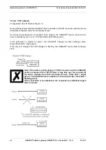
Page 42: ...5 3 1 TCP server TCP server Send Receive Port 23 Transparent data exchange with fieldbus DeviceNet Data structure 15 3 2 UDP Data structure 15 3 2 1 UDP with one remote participant Configuration EL IP Address Target 0 If the parameter is 0 another UDP participant has to send a UDP packet to the UNIGATE first the UNIGATE remembers the IP address of the sender and sends it back there ...

Page 43: ... to the UNIGATE 2x consecutively Note This mechanism was built in the UNIGATE for security reasons 15 3 2 3 UDP Configuration EL IP Address Target 0 If this parameter is set with a valid IP address the UNIGATE sends the process data indepen dently The process data is sent there until a remote participant with another IP address sends a packet to the UNIGATE then the UNIGATE behaves as described ab...

Page 44: ...n can be established Note If the Client terminates the connection during communication i e the UNIGATE sends the TCP IP packets system error 14 will be displayed on the LED s Note There is no information about the Link State e g if a RJ45 connector is connected to a counterpart station Note Automatic timeout after 45 seconds if there is no Acknowledge ACK from the counter part when a TCP IP packet...

Page 45: ... cyclically every 17 ms The Power State LED flashes green If the participant is started as server the UNIGATE changes to data exchange state Power State LED bright green If the server is stopped the LED changes to flashing the UNIGATE leaves data exchange state Note If the cable is pulled during a TCP IP connection and the UNIGATE sends a message to the TCP IP server it may take up a few seconds t...

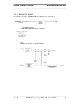
Page 46: ...E fieldbus gateway UNIGATE EL DeviceNet V 1 0 46 Deutschmann Automation GmbH Co KG Implemented protocols in UNIGATE EL 15 3 5 Modbus TCP server The UNIGATE is Server on the Ethernet side and waiting for a connection ...

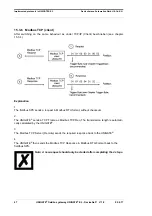
Page 47: ...4 Explanation 1 The fieldbus SPS sends a request in Modbus RTU format without checksum 2 The UNIGATE sends a TCP Frame as Modbus TCP Req The transmission length is automati cally calculated by the UNIGATE 3 The Modbus TCP Server Remote sends the required response back to the UNIGATE 4 The UNIGATE then sends the Modbus TCP Response in Modbus RTU Format back to the fieldbus SPS Note A new request sh...

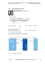
Page 48: ...Server The UNIGATE acts as Dual Port RAM Note Modbus Slave ID is not evaluated Maximum query length FC3 125 3 122 Byte 61 registers FC4 Maximum Write contract length at Address 0x0000 raw value FC16 125 7 118 Byte 59 registers For more information refer to figure 1 Introduction of the Universal Modbus server protocol l Figure 1 Universal Modbus server protocol ...

Page 49: ...e evaluated in the script There is a Exception Response 2 if a register address from and inclu ding 512 raw value is described If you try to write over the memory space of 1024 Byte it is automatically limited to 1024 There is no Exception Response Transferred to Little Endian Format Note FC1 Coil status Client reads Coil As start address you have to take a multiple of 8 Starting with 0 Thus 0 8 1...

Page 50: ... data Data structure 15 3 8 2 Data structure Ethernet side According to Modbus RTU Master Definition Supported functions Read coil status FC1 No of Points Bit Read input status FC2 No of Points Bit Read multiple register FC3 No of Points Word Read input registers FC4 No of Points Word Force single coil FC5 No of Points not used fix 1 Bit Preset single register FC6 No of Points not used fix 1 Word ...

Page 51: ...ind the other Up to 22 requests can be configured Additional configuration possibilities in the setting Req Modbus Function jump to Req 1 jump to 1 request entry disable this Req skip this request and perform the next request entry 10ms adjustable in 10ms steps hex Enter in hexadecimal style dec Enter in decimal style Byte Counting in bytes starting at the position Null Attention For read commands...

Page 52: ...ocol description see Chapter 15 3 1 15 4 1 Erstinbetriebnahme Quick Start Upon delivery the device is in an operable state Information DHCP is not supported 1 EL IP Addresse assigned WINGATE or UNIGATE Scantool 2 Configure blocklength 0 255 fieldbus input output via WINGATE e g 8 byte each 3 Set DeviceNet address and baud rate via DIP switch 4 Establish DeviceNet connection 5 Start UNIGATE in Data...

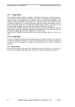
Page 53: ...ys sends and only then when the trigger byte is changed Accordingly the application program in the control in Normal mode cannot detect whether the gateway has received several identical telegrams If Trigger Byte mode is activated the gateway increments the trigger byte each time a telegram has been received The first byte in the fieldbus input output data buffer is used as the trigger byte if thi...

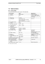
Page 54: ... H 5 Installation position Any 6 Weight 160 g 7 Operating temperature 40ºC 85ºC 8 Storage transport temperature 40 ºC 85 ºC 9 Atmospheric pressure during operation during transport 795 hPa 1080 hPa 660 hPa 1080 hPa 10 Installation altitude 2000 m 4000 m Unrestricted Restricted Ambient temperature 40ºC 11 Relative humidity Max 80 No condensation no corrosive atmosphere 12 External power supply 10 3...

Page 55: ...er slave Master slave Multimaster CSMA CD 4 Number of users Transmitters Receivers 32 32 1 1 32 32 512 512 5 Cable length Maximum Baud rate dependent 500 m 125 kB 500 m 250 kB 250 m 500 kB 100 m 15 m no 1200 m 93 75 kBd 1200 m 312 kBd 500 m 625 kBd 250 m 100 m 6 Bus topology Line Point to point Line Star 7 Data rate Maximum Standard values 500 kBit s 125 kB 250 kB 500 kB 120 kBit s 2 4 k B 4 8 k B...

Page 56: ...22 6 17 UNIGATE fieldbus gateway UNIGATE EL DeviceNet V 1 0 56 Deutschmann Automation GmbH Co KG Technical data Table Technical data of the interfaces and ports on the module ...

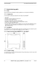
Page 57: ...iceNet cable generally this cable is already installed on site 10 33 V DC power supply DIN 19240 Type file or EDS file and user manual in chapter 13 2 you can find a sample EDS file the user manual can be ordered separately or downloaded free of charge from our homepage at www deutschmann de 17 3 Installation The UNIGATE EL DN module features protection type IP20 and is thus suitable for switch ca...

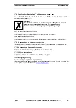
Page 58: ...to the DeviceNet at the interface labelled DeviceNet 17 8 Ethernet connection Connect the device to the Ethernet network at the interface X5 with the label RJ45 Ethernet 17 9 Connection to the process device Please also read the manual for the process device when commissioning the process device 17 10 Connecting the supply voltage Please connect 10 33 DC voltage to the terminals provided for this ...

Page 59: ...m to midday and from 1 pm to 4 pm Friday from 8 am to midday CET Deutschmann Automation GmbH Co KG Carl Zeiss Straße 8 D 65520 Bad Camberg Germany Central office and sales department 49 6434 9433 0 Technical Support 49 6434 9433 33 Fax sales department 49 6434 9433 40 Fax Technical Support 49 6434 9433 44 E mail Technical Support support deutschmann de 18 1 Returning a device If you return a devic...

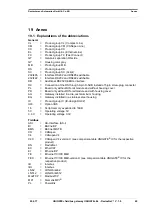
Page 60: ...n screw plug connector PL Board only without DIN rail module and without housing cover PD Board only without DIN rail module and with housing cover AG Gateway installed in a die cast aluminum housing EG Gateway installed in a stainless steel housing IC Product group IC IC design DIL32 IO8 Option I O8 16 Script memory expanded to 16KB 5V Operating voltage 5V 3 3V Operating voltage 3 3V Fieldbus ASI...

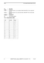
Page 61: ... UNIGATE IC for the respective product PBDPX ProfibusDP version X see comparison table UNIGATE IC for the respective product PBDPV0 ProfibusDPV0 PBDPV1 ProfibusDPV1 RS Serial RS232 485 422 19 2 Hexadecimal table Hex Decimal Binary 0 0 0000 1 1 0001 2 2 0010 3 3 0011 4 4 0100 5 5 0101 6 6 0110 7 7 0111 8 8 1000 9 9 1001 A 10 1010 B 11 1011 C 12 1100 D 13 1101 E 14 1110 F 15 1111 ...

Page 62: ......

Reviews: