21.4.15
Instruction manual UNIGATE
®
IC - Powerlink V. 2.3
43
Deutschmann Automation GmbH & Co. KG
Appendix
Slot X 1 (ZIF-socket)
PIN 1 of the IC is located up at the lever of the ZIF-socket.
Never place the IC into the socket back to front!
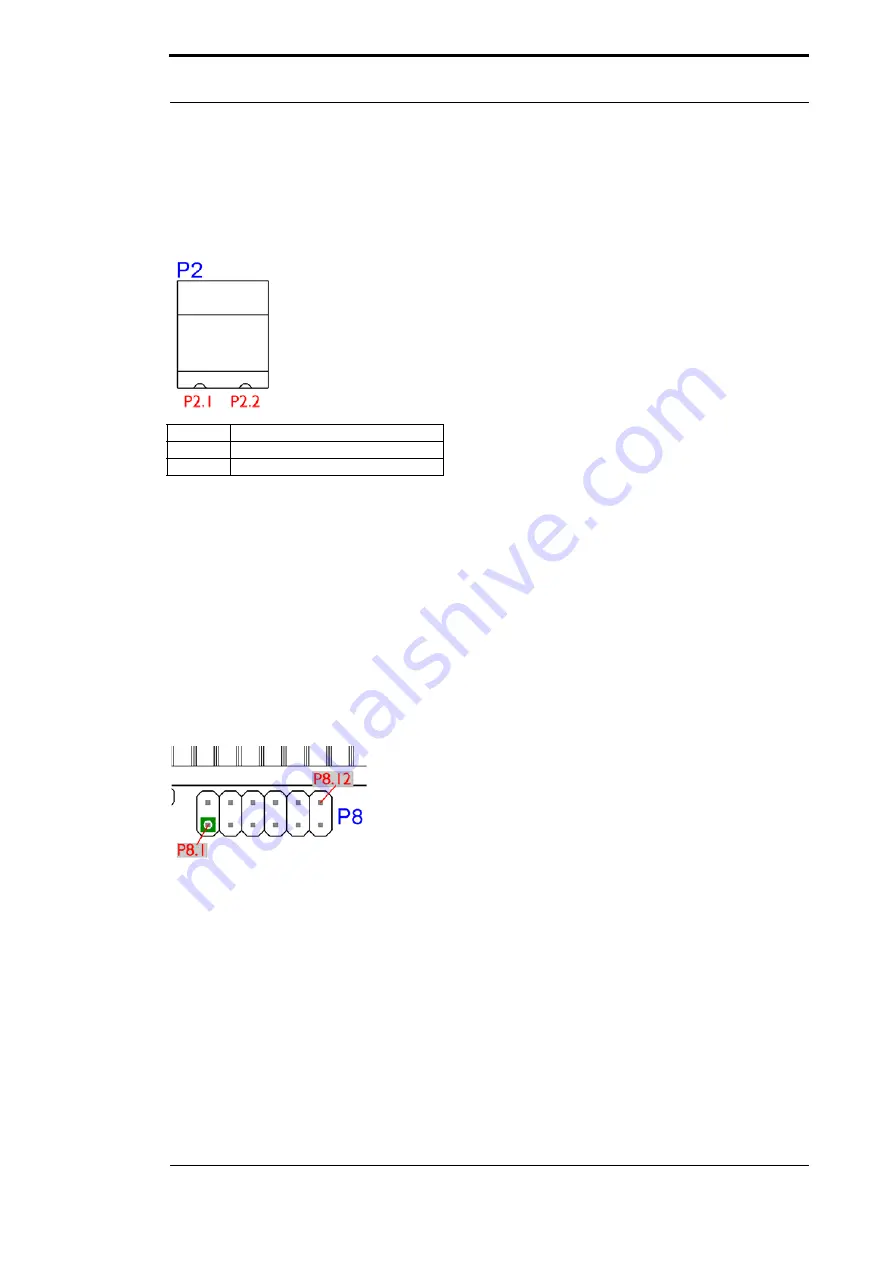
P 2
Pin
Signal
Pin 1
24 V DC
Pin 2
Ground
The basis board is supplied with voltage through this plug connector.
P 3 (AMP)
Powerlink plug connector, for the assignment of the connector see chapter 16.2.2.2.
P 4
Earth terminal 6.3 mm for basis board.
P 7
This plug is the basis board’s serial connection to the customer’s device and the connection to
the PC (Debug-interface).
For the pin assignment see chapter 16.2.2.1.
P 8
The illustration shows the arrangement of the pins. On this connector strip the signals of the
serial connection between IC and RS-drivers are wired. For an initial development you will prob-
ably also use an existing driver in your application. In order to exchange it later on, you can also
directly take the signals of the serial interface here.


