21.4.15
Instruction manual UNIGATE
®
IC - Powerlink V. 2.3
45
Deutschmann Automation GmbH & Co. KG
Appendix
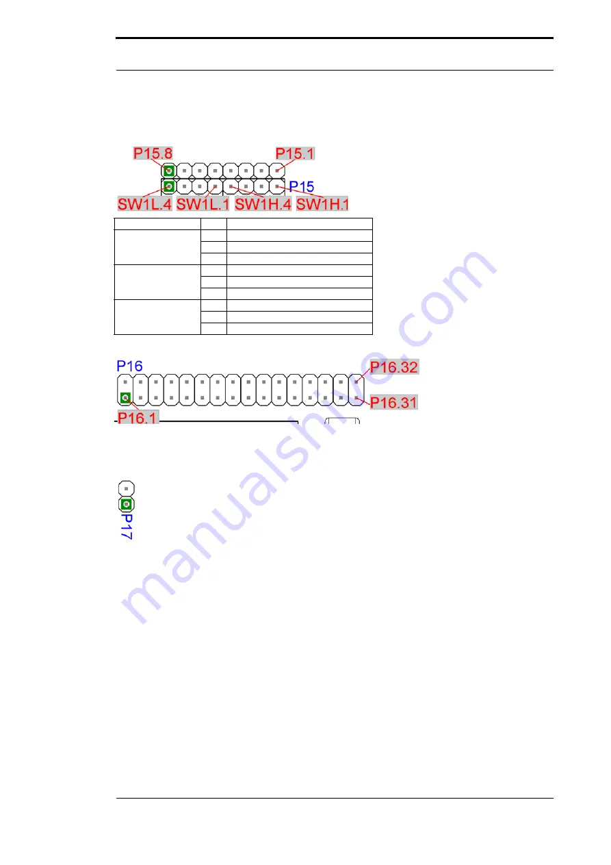
Basically the same applies as for P 14, with the exception that different input bits of the shift reg-
isters are wire.
Connection
Pin
Meaning
P 12
1
Input 1
.....
.....
8
Input 8
SW1H
1
Input 17
.....
.....
4
Input 20
SW1L
1
Input 21
.....
.....
4
Input 24
P 16
All digital outputs of the shift registers are available here. Additionally the LEDs D9, D15..D18,
D20 are connected to the shift registers.
P 17
With P17 the UNIGATE
®
IC can be brought into the configmode. If the jumper is plugged and if
the UNIGATE
®
IC is restarted (by power off and power on or by reset), then the UNIGATE
®
IC
will start in the configmode. In order to use the configmode with Deutschmann software tools the
interface of the board has to be in RS232-position and the PC has to be connected with the „nor-
mal“ interface, where otherwise your application is connected to.
See also chapter 7.2.
SW1H, SW1L, SW5H, SW5L
The rotary switches SW1H, SW1L, SW5H, SW5L are plugged into the base boards and can be
removed if required. As a default the rotary switches are plugged in and can be read in through
the basis board’s shift registers base boards (see also chapter 5 for it).


