Hardware design
Deutschmann Automation GmbH & Co. KG
12
Instruction manual UNIGATE
®
IC - PROFINET 1Port V. 3.4
27.11.20
3
Hardware design
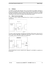
This chapter gives basic advise, that is required in order to load UNIGATE
®
IC into your own
hardware designs. In the following all ports of UNIGATE
®
IC are described in detail.
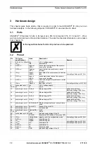
3.1
Ports
UNIGATE
®
IC features 32 pins in its layout as a DIL 32 component. Pin 10 -12 and 21 - 23 as
well are not wired due to the electrical isolation. The exact mechanical dimensions can be taken
from chapter 15.
In the layout boreholes for ALL 32 pins have to be planned.
3.2
Pinout
Pin
Technical
specifications
Name
Description
Remark
1*
3.3V ± 5% < 390mA Vcc
+3.3V voltage supply
2
IN
Logic
-BE
boot enable
3
OUT
Driver
Load out
(SS0-)
strobe signal output data of the synchro-
nous, serial interface
4
OUT
Driver
Data out
(SS1-)
output data of the synchronous, serial
interface
5
IN
Logic
Data in
(MISO)
input data of the synchronous, serial inter-
face
internally pulled up with 10 k
6
OUT
Logic
Load in
(MOSI)
strobe signal input data of the synchro-
nous, serial interface
7
OUT
Driver
Clock
(SCK)
clock pulse signal for synchronous, serial
interface
8
IN
Reset
-Reset in
reset-input of the IC
internally pulled up with 100 k
9*
connected to pin 1
Vcc
+3.3V voltage supply
10-12 nc
nc
no pin
13
according to norm
RJ45_6
Ethernet-signal RD-
galvanically isolated
insulation voltage 1000 Vrms
14
according to norm
RJ45_3
Ethernet-signal RD+
galvanically isolated
insulation voltage 1000 Vrms
15
according to norm
RJ45_2
Ethernet-signal TD-
galvanically isolated
insulation voltage 1000 Vrms
16
according to norm
RJ45_1
Ethernet-signal TD+
galvanically isolated
insulation voltage 1000 Vrms
17
according to norm
LED-LINKACT Ethernet linkpulses found / network data
traffic
18
according to norm
Error-LED
Anode of the red LED
19
according to norm
nc
not connected
20
according to norm
Ground (PE)
earth
21-23 nc
nc
no pin
24*
connected to pin 32 GND
ground supply voltage of the IC
25
LED-PN
bus status LED (Anode of the green LED)
26
IN
Logic
-Config Mode signal to start the configuration mode
internally pulled up with 10 k
27
OUT
Logic
DbgTX
serial Debug TX
28
IN
Logic
DbgRX
serial Debug RX
internally pulled up with 10 k
29
IN
Logic
RX
serial data RX
internally pulled up with 10 k
30
OUT
Logic
TX
serial data TX
31
OUT
Logic
TE
transmit enable
32*
GND
GND
ground supply voltage of the IC
Summary of Contents for UNIGATE IC-PROFINET
Page 2: ...Manual Art No V3641E...
Page 48: ......

