User Manual DEV 1953
100
Copyright DEV Systemtechnik GmbH 2015-2017
5.7
Control via Remote Interface: Leitch Protocol
5.7.1
Leitch Protocol Overview
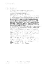
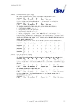
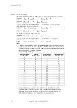
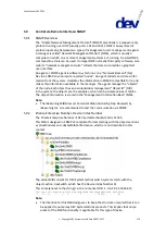
Like the Sandar Prosan protocol, the implementation of the Leitch protocol pro-
vides a standard for the communication between the device and a host. The inter-
face can be used for the monitoring and for the switching of the device. Within the
Leitch protocol standard it is distinguished between two protocol modes: the Leitch
Terminal Protocol and the Leitch Pass-Through Protocol. DEV Systemtechnik has
implemented a subset of the Leitch Pass-Through Protocol. Only one Leitch
Terminal Protocol command is implemented: "Enable Reporting" is the command
to switch to the Leitch Pass-Through Protocol mode.
The Leitch protocol is implemented to work via TCP/IP on port 23 (standard Telnet
port), and/or via the serial interface.
Note:
The Leitch protocol is available only if "Leitch" is selected within the CPH setup
of the Web Interface; please refer to chapter 5.5.7.2.3. If it is intended to use
the serial interface to control the device via Leitch protocol, the settings of the
serial interface have to be configured accordingly (chapter 4.4.1.1).
If "Echo in Local Mode" is disabled (factory default), the device responds in
Local Mode with the Leitch Error Message (see below) to any valid Leitch com-
mand which returns a response in Remote Mode. If enabled, the responses are
equivalent to the responses in Remote Mode. "Echo in Local Mode" can be en-
abled or disabled within the CPH setup of the Web Interface.
The Leitch protocol implementation on this device distinguishes between "Indi-
vidual Switch Level Assignment" being enabled (factory default) or disabled.
The selection is performed via a check box in the CPH setup of the Web Inter-
face and has impact on the behavior of the "Request Crosspoint Status" com-
mand (chapter 5.7.4.5), and on the behavior of the "Direct Crosspoint Take"
switching command (chapter 5.7.4.6).
Basically the selection alters the perspective on the arrangement of the switch
modules within Leitch levels (
<Lvl>
) and destinations (
<Dest>
) in Individual
switching mode:
(a) If "Individual Switch Level Assignment" is enabled, the single switch
modules are addressed via the level, the destination is always "0", i.e.
- Level 0/Destination 0 ≡ the switch module in the first slot,
- Level 1/Destination 0 ≡ the switch module in the second slot,
- Level 2/Destination 0 ≡ the switch module in the third slot, (…).
(b) If "Individual Switch Level Assignment" is disabled, the level is assigned to
the groups and the destination is assigned to the single switch modules.
Some examples:
- Level 0/Destination 0 ≡ the first switch module within Group 1,
- Level 0/Destination 1 ≡ the second switch module within Group 1, and
- Level 1/Destination 1 ≡ the second switch module within Group 2.
(c) In Simultaneous switching mode there is no distinction whether "Individual
Switch Level Assignment" is enabled or disabled. In both cases, the level is
assigned to the groups and the destination is assigned to the single switch
modules according to perspective (b).

