User Manual DEV 1953
Copyright DEV Systemtechnik GmbH 2015-2017
53
5.5.4.1
Group
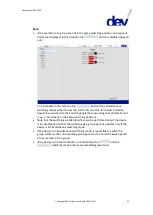
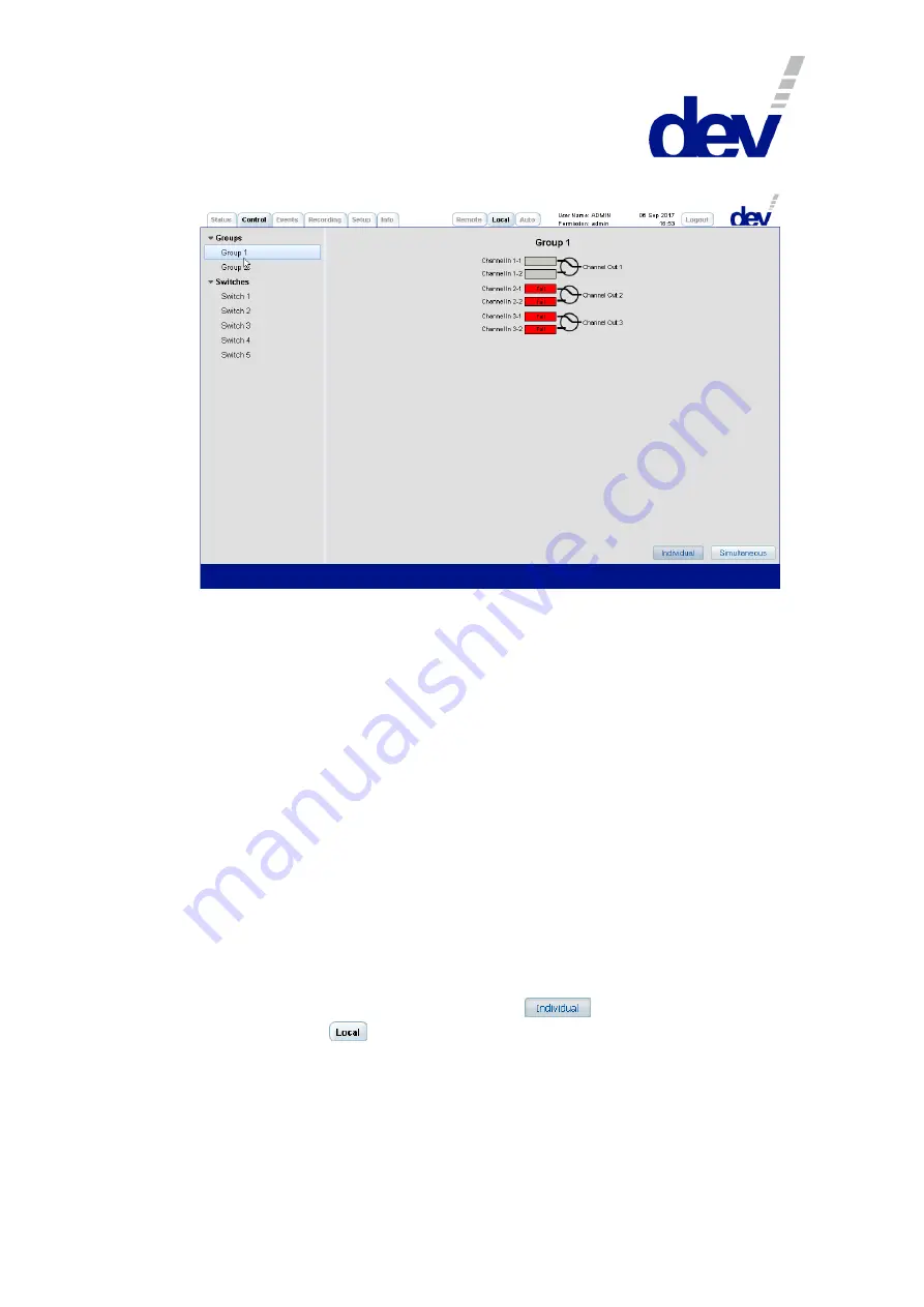
If a group is selected on the left side of the Control Tab, the corresponding group
panel appears on the right side where the simultaneous (!) switching of the switch
modules being member of the group can be performed.
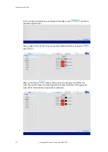
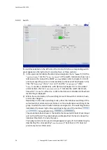
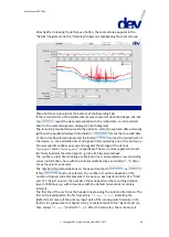
The screenshot above shows the device with "
Group 1
" activated, here -to
demonstrate simultaneous switching- the group is configured with the first three
switch modules as members. I.e. the initial group assignment (each module is
assigned to a separate group) was changed via the related setup functionality;
please refer to chapter 5.5.7.3.3.
The representation of each switch module is realized via two rectangles for the two
input ports and via a circle indicating the switch position.
For switch modules with RF level monitoring functionality (and with digital signal
monitoring functionality, respectively) the present RF levels (and the digital signal
quality information, respectively) of each input port are visible within the
rectangles. A red background implies, that the RF level is below the RF threshold
level (and the digital signal quality is "Fail", respectively), it is green otherwise. The
background color of an input port appears in gray if it does not provide any status
information or if a port (which is capable of generating status information) is
disabled (chapters 5.5.4.2, 5.5.4.3, & 5.9.4.3.9.2).
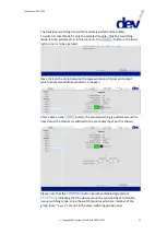
In the screenshot above, all members of the group are in the same switch position
indicated by the same type of circles. Also, the
button (lower right
corner) and to the
button (in the middle of the top) are active, indicating
Individual switching mode and Local Mode of the device.
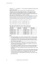
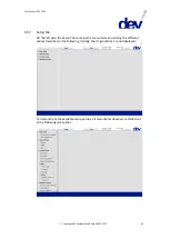
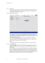
With these preconditions, simultaneous switching is performed as follows:

