
User Manual DEV 1953
Copyright DEV Systemtechnik GmbH 2015-2017
137
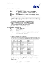
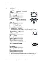
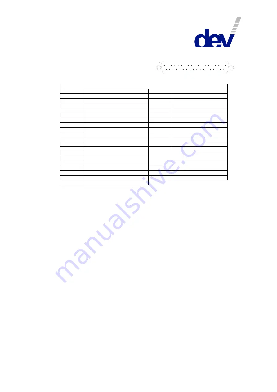
Digital Interface Connector (Options 56 & 57)
Connector:
Sub-D 37 (male)
Connector screws:
UNC 4-40
Digital Interface Connector
Pin
Functionality
Pin
Functionality
Pin 1
Output: Module 1 (normally open)
Pin 20
Input: Module 1
Pin 2
Output: Module 2 (normally open)
Pin 21
Input: Module 2
Pin 3
Output: Module 3 (normally open)
Pin 22
Input: Module 3
Pin 4
Output: Module 4 (normally open)
Pin 23
Input: Module 4
Pin 5
Output: Module 5 (normally open)
Pin 24
Input: Module 5
Pin 6
Output: Module 6 (normally open)
Pin 25
Input: Module 6
Pin 7
Output: Module 7 (normally open)
Pin 26
Input: Module 7
Pin 8
Output: Module 8 (normally open)
Pin 27
Input: Module 8
Pin 9
Output: Module 9 (normally open)
Pin 28
Input: Module 9
Pin 10
Output: Module 10 (normally open)
Pin 29
Input: Module 10
Pin 11
Output: Module 11 (normally open)
Pin 30
Input: Module 11
Pin 12
Output: Module 12 (normally open)
Pin 31
Input: Module 12
Pin 13
Output: Module 13 (normally open)
Pin 32
Input: Module 13
Pin 14
Output: Module 14 (normally open)
Pin 33
Input: Module 14
Pin 15
Output: Module 15 (normally open)
Pin 34
Input: Module 15
Pin 16
Output: Module 16 (normally open)
Pin 35
Input: Module 16
Pin 17
Output: Module 16 (normally closed)
Pin 36
Input: In_Common
Pin 18
Output: Out_Common
Pin 37
Input: In_Common
Pin 19
Output: Out_Common
Note:
•
Please refer to chapters 3.1.4, 3.2.26, & 5.4 for more information on the digital interface.
•
The digital outputs (pins 1…17) are realized as dry relay contacts, pins 18 and 19 are the common pins
(Out_Common).
If a contact is open, it means that the corresponding module is switched to the primary input port ("
In A
"). If it
is closed (i.e. it has the same electrical potential as the common pins), the module is switched to the
secondary input port ("
In B
"). An exception is pin 17 that indicates the status of module 16 as a normally
closed contact, i.e. contradictory to pin 16.
•
The digital inputs (pins 20…35) are realized with optocouplers with pins 36 & 37 as the common ground pins
(In_Common).
If the device is switched (from Local Mode or Auto Mode) to Remote Mode with Individual switching mode
activated and if no voltage is applied to a digital input, the corresponding module is switched to the primary
input port ("
In A
"). On the other hand, if a positive electrical potential (Option 56: n24 V, 5.8 mA and
Option 57: n12 V, 4.8 mA) is applied to a digital input, the corresponding module is switched to the
secondary input port ("
In B
").
If the device is switched to Remote Mode with Simultaneous switching mode activated, the potential on the
digital input of the first member of a group determines the switch position of the group.
If the device is in Remote Mode and Individual switching mode is activated, a rising slope on a digital input
forces the corresponding module to be switched to the secondary input port ("
In B
"); a falling slope switches
the module to the primary input port ("
In A
").
If the device is in Remote Mode and Simultaneous switching mode is activated, a rising slope on any (!) digital
input assigned to a module being member of a group forces the corresponding group to be switched to the
secondary input port ("
In B
"). A falling slope on any digital input assigned to a member of a group switches the
group to the primary input port ("
In A
").
1
3 7


