User Manual DEV 1953
Copyright DEV Systemtechnik GmbH 2015-2017
29
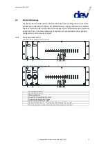
3.3.4
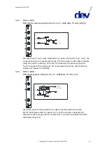
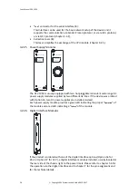
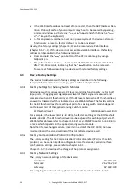
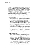
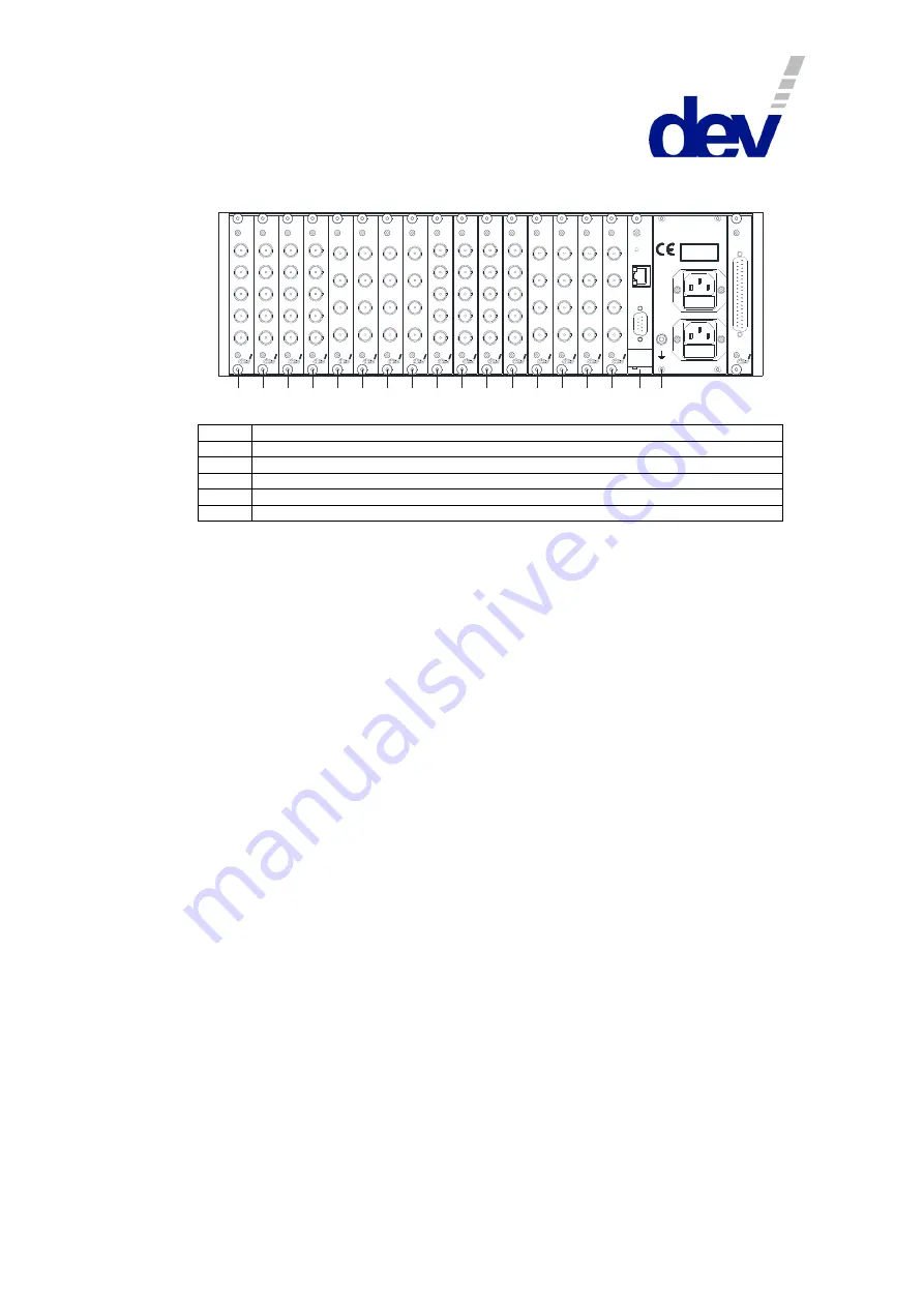
Rear Side DEV 1953 with 16 Modules (Digital Switching Application)
Rear View:
2
1
3
4
5
6
7
8
9
1 0
1 1 1 2
1 3
1 4
1 5
1 6
P
C
1 0 0 ...2 4 0 V
D is c o n n e c t p o w e r
W A R N IN G :
b e fo re o p e n in g !
5 0 ...6 0 H z
5 0 V A
S u p p ly 2 - F u s e 2 A T
S u p p ly 1 - F u s e 2 A T
M & C 1
C o m
E th e rn e t
R e s e t
D E V 1 4 -0 0 8 9
In A
In B
O u t 1
O u t 2
O u t 3
D E V 1 4 -0 0 8 9
In A
In B
O u t 1
O u t 2
O u t 3
D E V 1 4 -0 0 8 9
In A
In B
O u t 1
O u t 2
O u t 3
D E V 1 4 -0 0 8 9
In A
In B
O u t 1
O u t 2
O u t 3
In B
M o n ito r
O u t
In A
D E V 1 1 -0 0 3 1
In B
M o n ito r
O u t
In A
D E V 1 1 -0 0 3 1
In B
M o n ito r
O u t
In A
D E V 1 1 -0 0 3 1
In B
M o n ito r
O u t
In A
D E V 1 1 -0 0 3 1
D E V 1 4 -0 0 9 4
In A
In B
O u t 1
O u t 2
O u t 3
D E V 1 4 -0 0 9 4
In A
In B
O u t 1
O u t 2
O u t 3
D E V 1 4 -0 0 9 4
In A
In B
O u t 1
O u t 2
O u t 3
D E V 1 4 -0 0 9 4
In A
In B
O u t 1
O u t 2
O u t 3
In B
M o n ito r
O u t
In A
D E V 1 1 -0 0 3 1
In B
M o n ito r
O u t
In A
D E V 1 1 -0 0 3 1
In B
M o n ito r
O u t
In A
D E V 1 1 -0 0 3 1
In B
M o n ito r
O u t
In A
D E V 1 1 -0 0 3 1
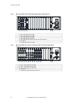
1…4
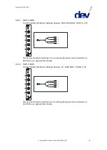
Slots 1…4 equipped with DEV 14-0089
5…8
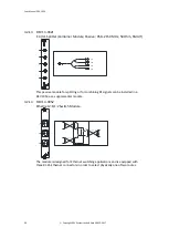
Slots 5…8 equipped with DEV 11-0031
9…12
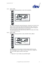
Slots 9…12 equipped with DEV 14-0094
13…16
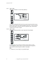
Slots 13…16 equipped with DEV 11-0031
C CPU module
P Grounding bolt, AC power plugs, and digital interface module (Option 56 or Option 57)
4
Installation Instructions
4.1
Scope of Delivery
1 * DEV 1953
equipped with switch modules, distribution amplifier modules,
splitter modules, and other options,
as ordered
1 * User Manual (this document)
4.2
Installation of the Product
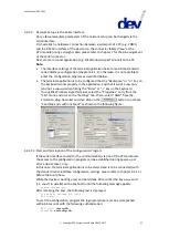
4.2.1
Mechanical Assembly
Please refer to the warnings in chapter 2.3 regarding the mechanical integration of
the product. For the integration in a 19" rack, the rack slots must be prepared with
rails for the chassis. After inserting the chassis in the rack, fix the chassis with four
screws to the rack at its rack mount flanges.
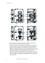
4.2.2
Grounding, Data Cables, and Power Connection
For the warnings with respect to "Grounding, AC Connection, Cables" please refer
to chapter 2.3.
The chassis needs to be connected to the 19" rack via a ground wire. The grounding
bolt (labeled
1
in the figures below) is located on the right at the rear side of the
product.
Take off the upper nut and the first washer of the grounding bolt and connect the
grounding cable, which must have a ring tongue terminal matching for the M4
fastening bolt. After that, the washer and the nut have to be tightened again.


