User Manual DEV 1953
Copyright DEV Systemtechnik GmbH 2015-2017
31
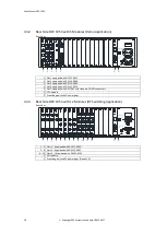
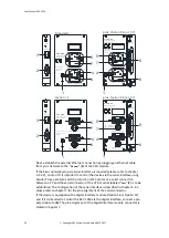
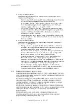
Finally, connect two power cords to the primary connectors (
4
&
5
). It is recom-
mended to use two separately fused phases of the available electrical outlets. If the
device was ordered with Option 14, the power cables have to be prepared. The
matching connectors are part of the delivery; the pin assignment is stated in
chapter 7.
Note:
It is
highly recommended
to power up the device after the installation of the
modules (chapter 4.2.5) and after the connection of all signal cables (chapters
4.2.3 & 4.2.4).
The power lines are fused separately; the fuse holders (
6
&
7
) are located
below the related power inlet (
4
&
5
). If a fuse has to be exchanged, unplug the
device completely and use 2 A T 5*20 mm glass fuses (4 A T 5*20 mm glass
fuses for devices with Option 14) for replacement only!
4.2.3
Connection of Optical Signal Cables
Only if the DEV 1953 is equipped with optical switch modules DEV 7462 and/or
DEV 7463, optical fibers have to be connected to the installed optical modules.
Please refer to the laser safety warnings stated in chapter 2.3!
If applicable, apply strain relieves to the optical fibers which are to be connected to
the installed optical modules in a way, that the connectors of the optical modules
are not stressed mechanically.
Sequentially, remove each optical connector protection cover at the device, and
plug in and tighten the corresponding connector from the optical fiber bundle(s).
Note:
The optical modules are available with different optical connector types, i.e.
FC/APC, E2000 HRL, or SC/APC.
Make sure, that the matching connectors are installed in the application.
4.2.4
Connection of RF Signal Cables
Apply strain relieves to the external RF signal cables which are to be connected in a
way, that the connectors of the device are not stressed mechanically.
When connecting RF cables to the installed modules, each connector providing a
thread is to be tightened with a torque wrench. For 75 Ohm F connectors the
applied torque should not exceed 4.5 Nm (39.8 lbf-in). In case of 50 Ohm
SMA connectors a torque wrench adjusted to 1 Nm (8.85 lbf-in) is to be used. If a
module is equipped with BNC connectors, make sure that the bayonet of each RF
connection is locked.
Note:
For 75 Ohm RF connectors, either female 75 Ohm BNC connectors or female
precision F connectors are applied. Make sure, that the applied connectors are
male 75 Ohm BNC connectors or male precision F connectors (with thin inner
conductor).
Each unused output port of a passive splitter module or of a distribution
amplifier module is to be terminated with an appropriate load (i.e. 50 Ohm
SMA (m), 75 Ohm F (m), or 75 Ohm BNC (m)) to achieve best amplitude
frequency response.
If all cables are connected, the device can be powered up.

